
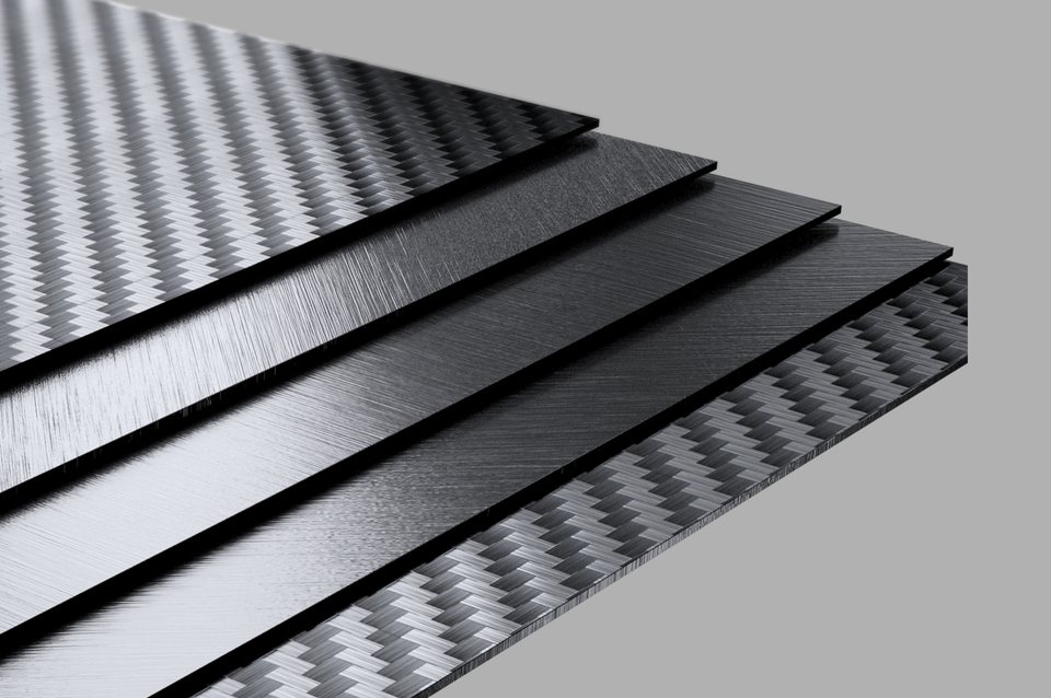
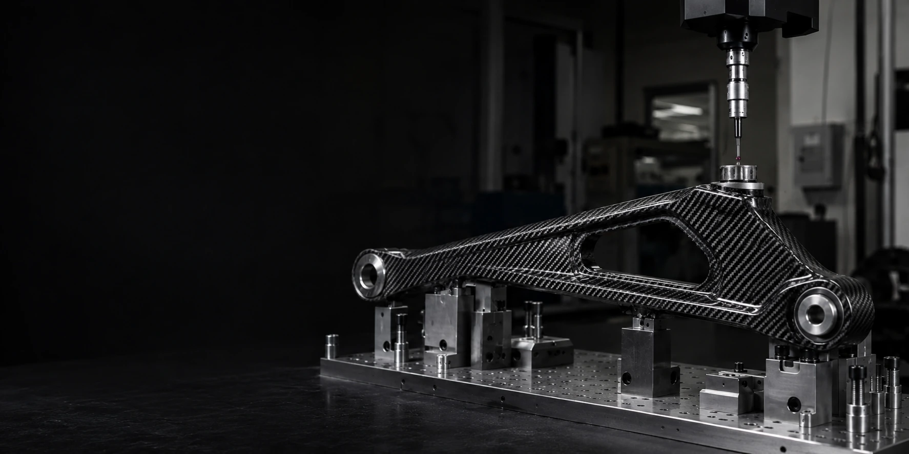
A Carbon Fiber OEM Manufacturer for Parts You Can Approve, Deliver and Reorder
Bring a concept, drawing, sample, or a carbon fiber part that has already gone wrong. NEXWAVE helps turn it into a manufacturable, validated and repeatable finished part.
Which Carbon Fiber OEM or ODM Model Fits Your Project?
The label is not the first decision. Start with what is already defined, what is still missing and who must own the missing work. A drawing that shows only the outside shape is not yet an OEM-ready product definition. A plate order that also needs a logo, retail packing and export documents is more than a cut-part purchase.
If an incomplete definition is treated as build-to-print OEM work, the manufacturer must either guess at the missing laminate, tolerances and interfaces or leave that work outside the quote. The first route can produce a part built to assumptions the customer never approved. The second can leave the project without anyone responsible for making the design manufacturable.
Choosing the model therefore changes whether the buyer receives manufacturing execution against a complete definition or the engineering work needed to create that definition first. Choosing the right responsibility model early helps protect four practical results.
Start from what you can provide
Four visas · pick by what you already hold
 VISA · OEM
OEM
You have a complete product design, released drawings and technical requirements.
 VISA · ODM
ODM
You have a function, interface, market or appearance objective, but not a complete product definition.
 VISA · CONTRACT MFG
Contract Manufacturing
You provide the technical, process and quality framework.
 VISA · PRIVATE LABEL
Private Label
You choose an existing NEXWAVE product or an approved light-modification route for your brand.
 CASE 01 · RECLASSIFIED
Drawing with three dimensions
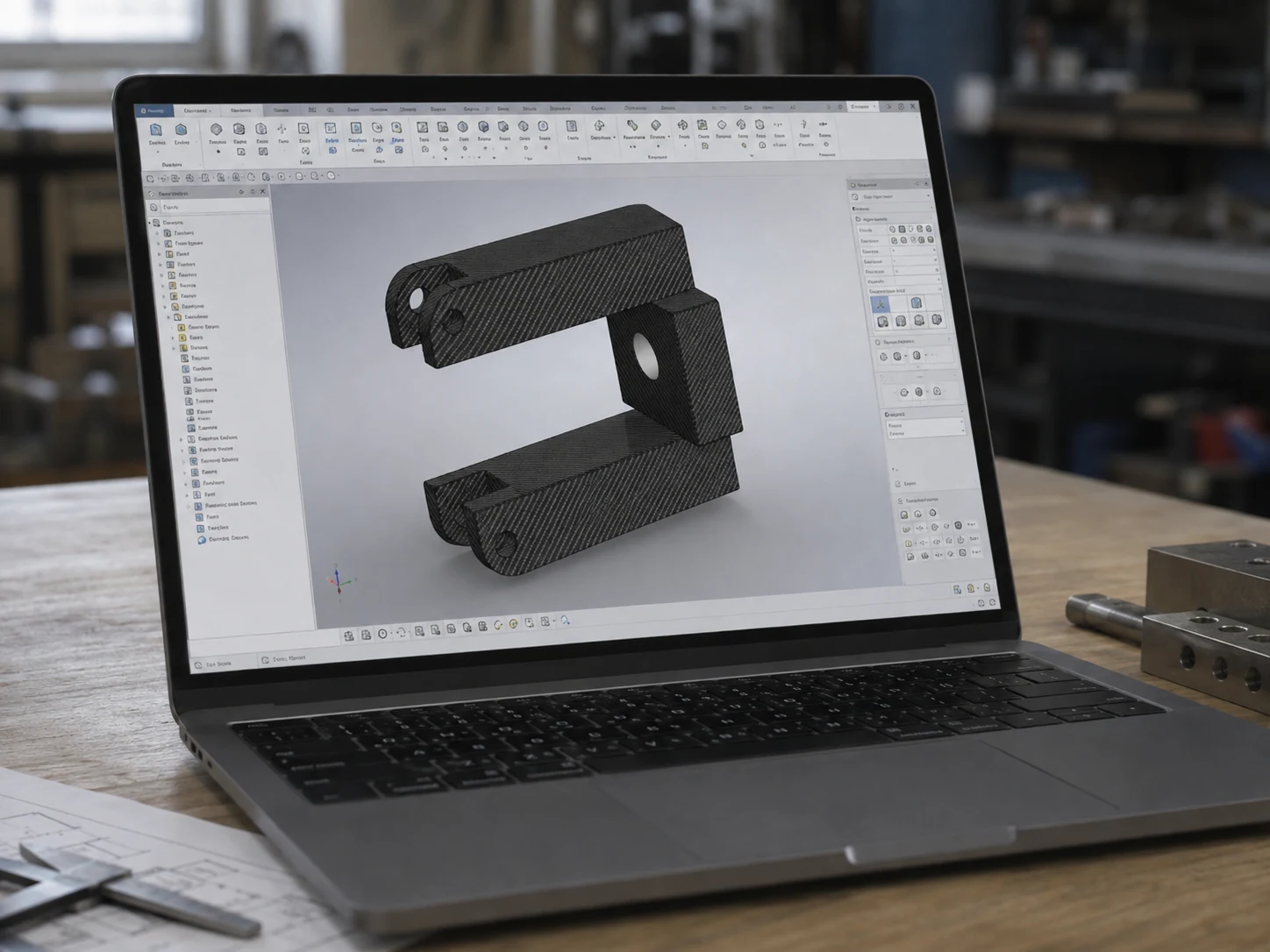
One customer initially asked NEXWAVE to "make the part from the drawing." The drawing contained only overall length, width and height. There was no laminate, material specification, tolerance scheme or mounting-interface definition. The project was reclassified as a joint ODM development: NEXWAVE developed the laminate and tolerance direction, while the customer confirmed the functional target and installation interface. The first sample was accepted, and the customer later added three related parts.
 CASE 02 · PRIVATE LABEL
More than a cut-part purchase
In another project, the buyer appeared to need cut carbon fiber plate. The real delivered order also required finish, logo printing, custom packing and export documents. Treating it as private-label supply closed those responsibilities before production instead of leaving the buyer to coordinate them after the parts were made.
Keep approval separate from execution
Clearance table · who signs each line
Physical logo application, label application and branded packing execution are included only when they are listed in the confirmed supplier scope.
NEXWAVE does not silently take responsibility for complete vehicle approval, safety-system certification, implant biocompatibility or an undefined end use. Those decisions stay with the customer or the qualified third party named in the project unless a specific, bounded NEXWAVE task is agreed in writing.
Turn a Drawing or Concept Into a Composite-Ready Manufacturing Definition
A 3D model can describe the outside shape and still leave the important carbon fiber decisions unanswered. The load path, laminate, tight radii, thickness transitions, release direction, mounting interfaces and inspection datums determine whether the part can be laid up, removed from the tool, machined, measured and assembled.
Those items change different parts of the finished result. Load path and fiber direction affect whether the part bends, twists or cracks where the assembly puts force into it. Radii and draft affect whether the fabric can lie against the tool without bridging or wrinkling and whether the cured part can be removed without damage. Inspection datums give holes and mating faces a common reference; without them, a supplier can measure individual dimensions yet still miss the pattern or position that controls fit.
What NEXWAVE changes before tooling
NEXWAVE converts the intended use into composite-manufacturing decisions. The review can cover:
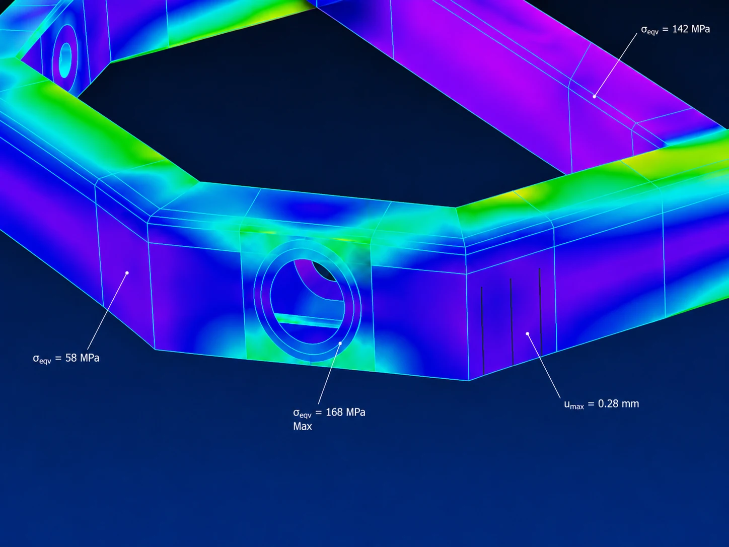 FIG 2.A · LAMINATE & DATUM REVIEW
Project example: a UAV frame that was not ready to manufacture
An anonymous UAV customer supplied an exterior STEP model, several photographs and a finished-weight target below 350 g. The file did not define a laminate, material, tolerances, mounting interfaces or inspection basis.
| What engineering found | Customer-approved change | What the change prevented or made measurable |
|---|---|---|
| A 1.2 mm wall passed through several tight turns, including internal radii below 3 mm. | Increase the relevant radii to at least 5 mm and add smoother transitions. | Reduced the risk of bridging, folds and resin accumulation in the tight regions. |
| Four motor holes had no common positioning basis. | Add three 6 mm datum holes for CMM setup and inspection. | Made the motor-hole pattern measurable against one repeatable reference. |
| The original layup direction did not address the combined loading. | Use a project-specific [0/±45/90]s direction with three local reinforcement plies around each motor-hole region. | Connected the laminate and local reinforcement to the structural and mounting problem. |
| The model moved abruptly from 1.2 to 2.0 mm. | Add a 1:20 tapered thickness transition. | Reduced the abrupt laminate step that could create a local manufacturing and stress concentration problem. |
| One area had negative draft. | Add two degrees of draft in the affected release region. | Allowed the part to leave the tool without forcing or damaging it. |
The customer received a marked drawing, DFM report, revised STEP file, risk list, material/process direction, validation plan and cost comparison for this project. Those missing composite decisions were found while they could still be changed on the model, before the customer had paid for a tool and an unusable sample. The laminate and document set remain specific to the part and the risk.
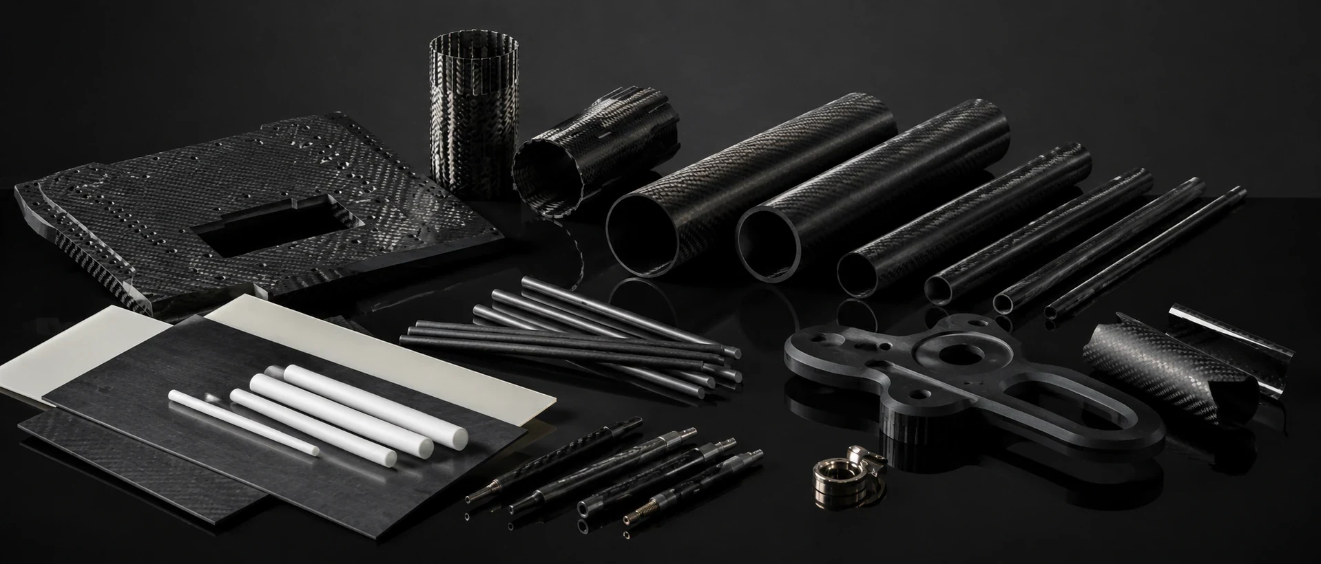 GATE 03 APPROACH · THE BACK SIDE DECIDES
Engineer the Carbon Fiber Interfaces That Decide Whether the Part Fits
The front surface may sell the product, but the back side usually decides whether it can be assembled. Hole patterns, inserts, clips, bearing seats, bond lines, flanges, edge conditions and local reinforcement all have to work with the customer's real mating part.
Close the interface before the part reaches assembly
NEXWAVE starts by identifying the mounting datums and the features that actually control fit. The team then connects those features to the laminate, local reinforcement, CNC route, insert or bonding process and inspection method.
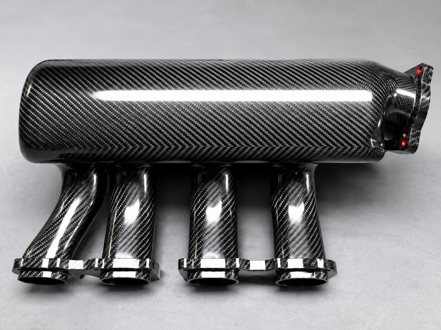 FIG 3.A · INSERT
For an insert
That may mean defining the hole, laminate support, installation method and torque check together.
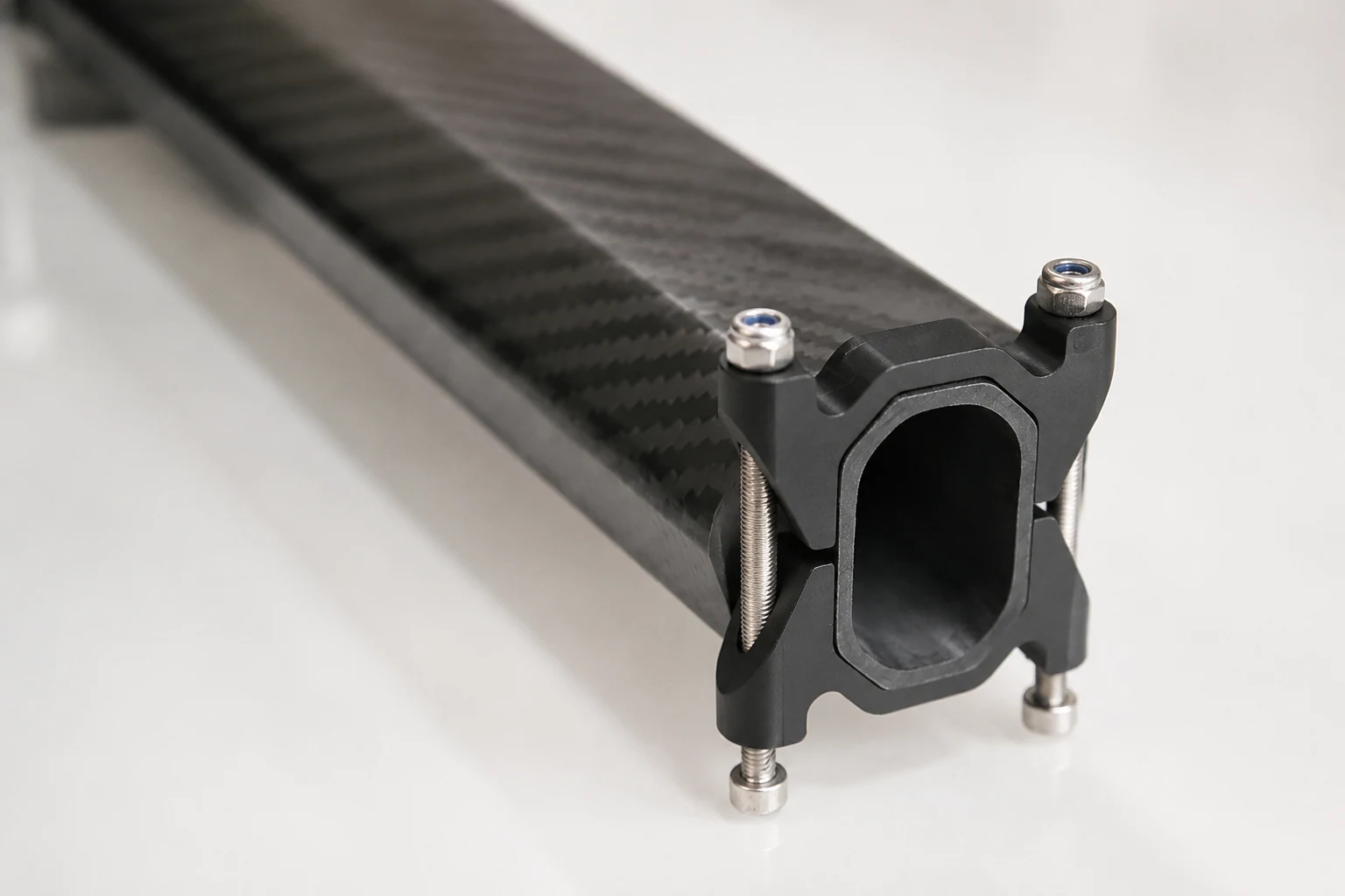 FIG 3.B · FLANGE
For a flange
It may mean defining flatness, trim position, seal contact and the measurement datum as one interface.
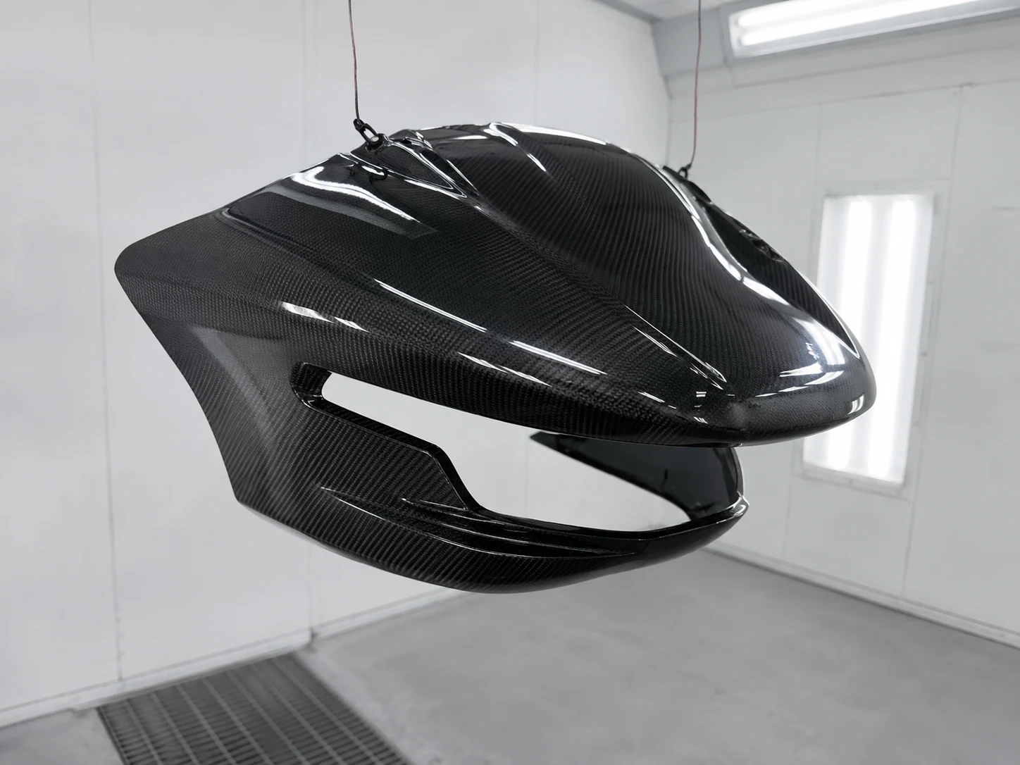 FIG 3.C · COVER
For a contoured cover
It may require a target assembly, scan or checking fixture rather than relying on the outer CAD surface alone.
CASE · ROBOTIC END EFFECTOR
In one robotic end-effector project, the carbon fiber body included four threaded inserts, two positioning-pin holes and a sealing flange. NEXWAVE repeated CMM inspection after insert installation and physically mated the part to the customer's aluminum adapter. That sequence checked the interface after the operation most likely to move it, rather than only before the hardware was installed.
Choose Carbon Fiber Materials, Processes and Tooling as One Production System
Starting with "use T800," "make it in an autoclave" or "build a production mold" can send the project in the wrong direction. Fiber grade, laminate, resin, molding route, tool and secondary operations must solve the same load, geometry, appearance, quantity and delivery problem.
A material can be technically capable and still be the wrong commercial or manufacturing choice because the fiber grade is only one part of the structure. A higher-grade fiber placed in the wrong direction does not stop a panel twisting, and it does not protect a poorly supported hole from local bearing damage. A resin that meets room-temperature strength requirements may still soften, discolour or lose bond performance in the actual heat, UV, moisture or chemical environment. Paying for the material name alone can therefore increase part cost without fixing the failure the buyer is trying to prevent.
Process and tooling create another constraint. An autoclave can provide controlled heat and pressure, but it cannot make fabric conform to an inaccessible corner or release a part from negative draft. A production tool can support repeat output, but it also freezes the geometry and tool split; if the interfaces are still changing, the buyer may pay to modify or replace it. A low-cost prototype route can be useful for checking shape, yet still be the wrong approval route when the sample must prove the surface, dimensions or process that later orders must reproduce.
Let the product target choose the route
| Product or program condition | What NEXWAVE reviews | Why it changes the buyer's result |
|---|---|---|
| Bending, torsion, local bearing or impact | Fiber direction, laminate balance, sandwich or local UD reinforcement | Bending can make a panel deflect out of alignment; torsion can twist mounting faces; bearing loads can oval a hole or split the laminate around an insert; impact can start delamination. The laminate is therefore arranged to control the failure that would stop the part fitting, carrying its defined load or staying usable. |
| Heat, UV, moisture, salt or chemical contact | Resin, adhesive, coating and environmental validation | These conditions can soften the resin, weaken a bond, change the surface colour or cause coating damage. Reviewing them before material approval helps prevent a part that passed at room temperature from losing fit, finish or bond performance in service. |
| Tight geometry, deep draw, undercut or variable thickness | Layup access, release, molding route, tool split and thickness transition | Fabric that cannot reach or compact against the tool can leave wrinkles, resin-rich areas or thickness variation; an undercut can trap the cured part. Solving access and release before tooling helps avoid rejected samples, forced demolding and tool rework. |
| Prototype, multiple variants or changing demand | Plate-and-CNC, prototype tool, multi-part fixture or production-intent tool | A route that is economical for one shape can become expensive when every revision needs a new tool; a flexible prototype route can become slow when volume stabilizes. Matching the route to the current stage helps the buyer prove changes without discarding premature tooling, then move to repeat production when the design is ready. |
| Visible weave, painted finish or controlled edges | Tool face, material form, trim allowance and finish process | These choices affect weave alignment, print-through, pinholes, gloss, paint preparation and edge breakout. Designing them into the route helps prevent a structurally usable part from becoming unsellable or requiring manual refinishing because its visible surface or edge does not match the approved product. |
| Holes, inserts, bonding, assembly and inspection | CNC, drill support, fixtures, access and records | A molded blank still cannot enter the customer's assembly if a hole is out of position, an insert lacks laminate support or a bond face cannot be prepared and checked. Including these operations in the route turns the molded shape into the finished component the assembly actually needs. |
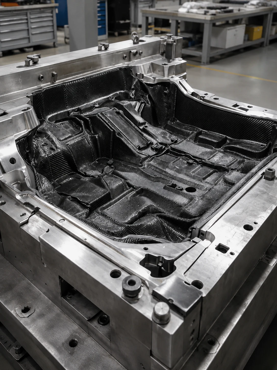 FIG 4.A · ONE ROUTE, ONE SYSTEM
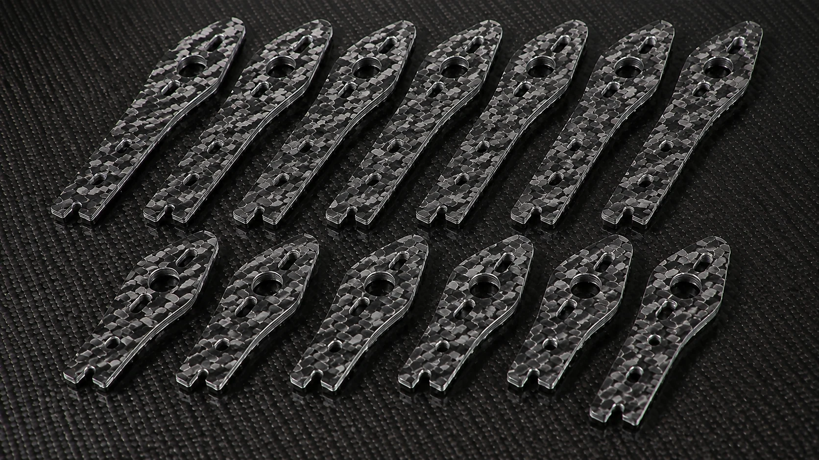
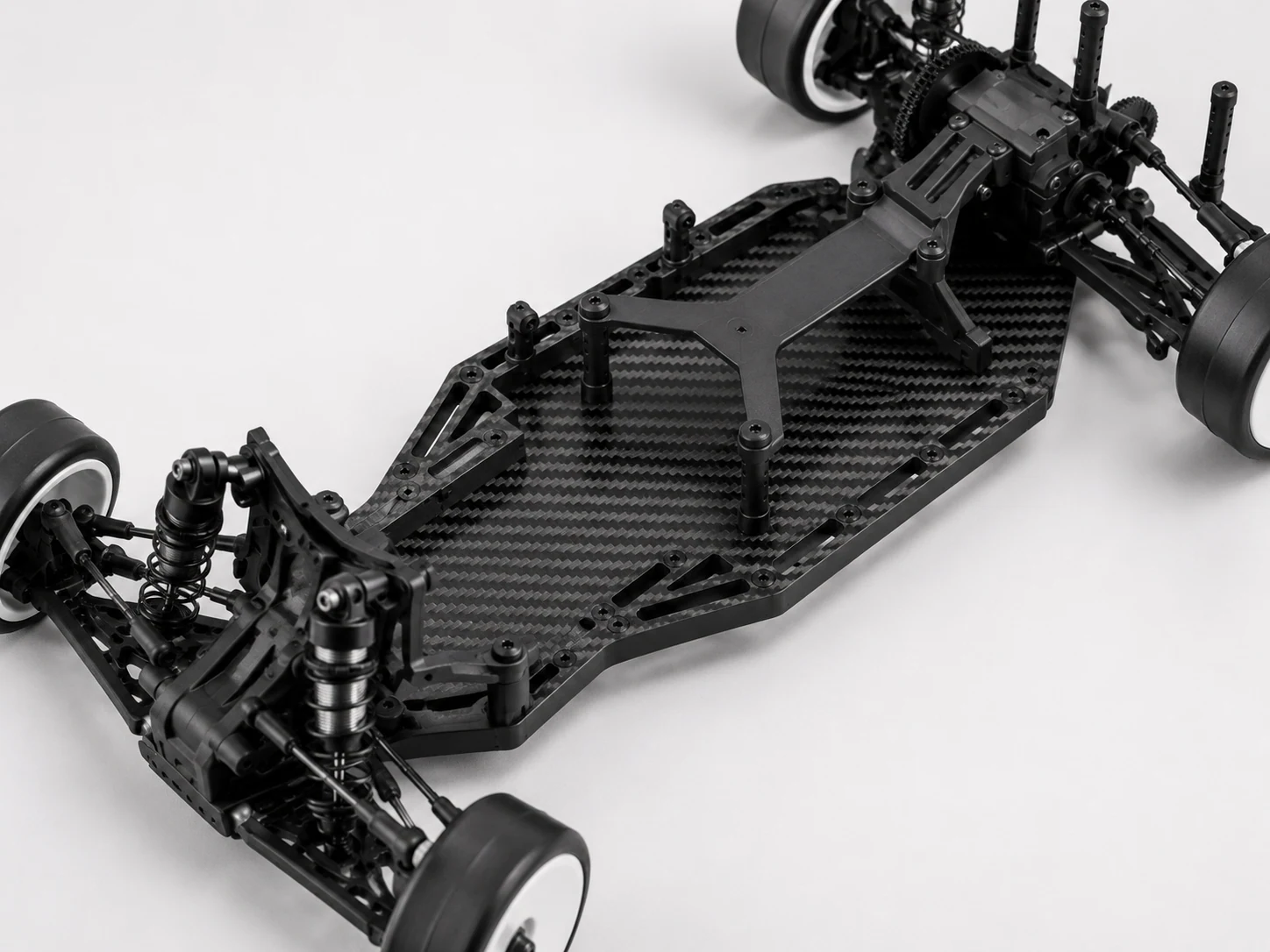
NEXWAVE has used a plate-and-CNC route with a multi-part fixture across 21 released industrial UAV frame-plate variants. The route matched a family with changing geometries and repeated machined features without forcing each variant into a separate molded-part assumption. That project does not make plate-and-CNC right for every frame. It shows how expected variants, feature access and production state can change the tooling decision.
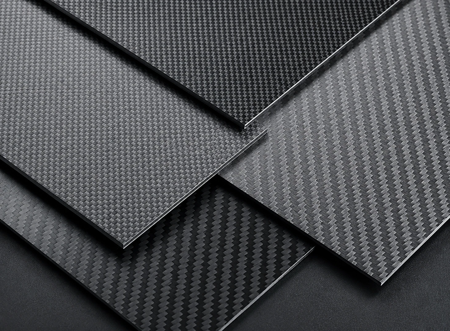 GATE 05 APPROACH · WHAT DOES A SAMPLE PROVE
Validate Carbon Fiber Samples for Appearance, Fit, Function and Production
A good-looking sample proves only that one part looked good. It does not automatically prove the mounting interfaces, structural requirement, environmental behaviour or repeat-production route.
Appearance, fit, function and production fail for different reasons and need different checks. A hand-finished appearance sample can hide how much polishing or repair one piece required. A fit sample can align correctly while using a laminate or tool that will not be used for production. A structural sample can pass a defined load yet say nothing about visible weave or whether the production fixture will hold every hole in position. One sample should only release the decision it was built and measured to prove.
Use the sample that answers the real risk
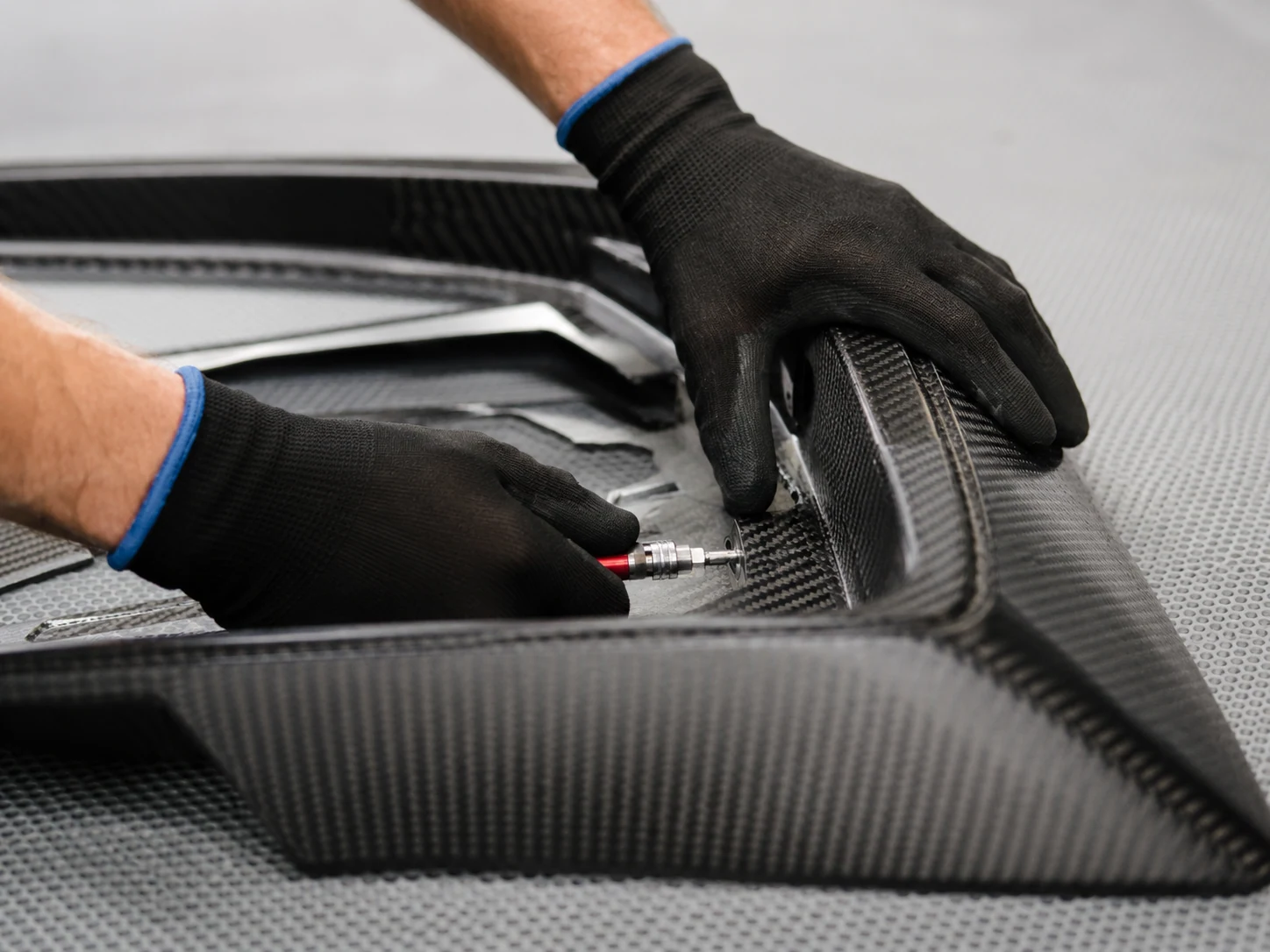 SAMPLE TYPE 01
Appearance
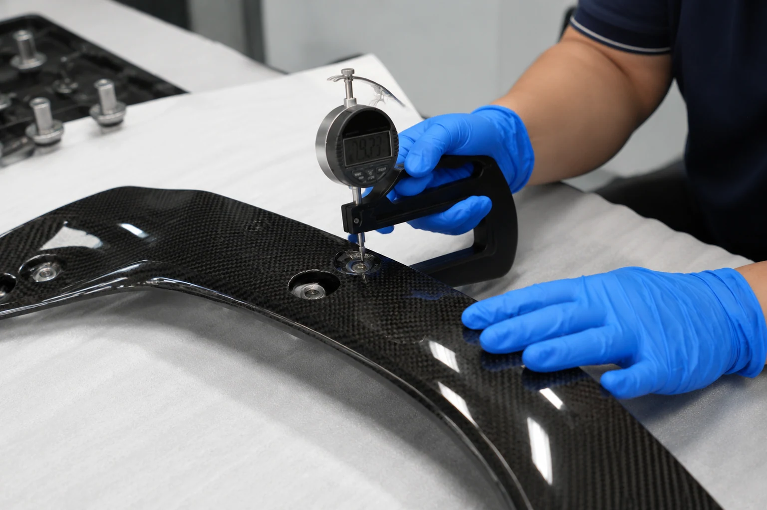
Answers: are the visible weave, gloss, colour, edges and allowed defects acceptable? Evidence: approved appearance reference, D65 visual record, gloss or colour result when required. Protects: prevents a visually inconsistent or hard-to-refinish surface from being repeated across parts the buyer cannot sell in the approved grade.
 SAMPLE TYPE 02
Fit and assembly
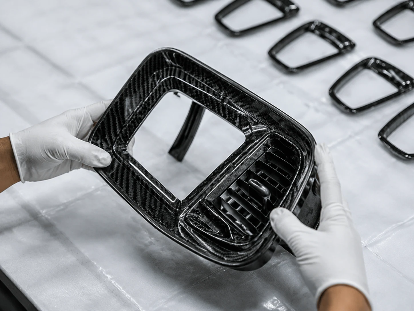
Answers: do the datums, holes, interfaces, clearances and adjacent parts work together? Evidence: CMM or fixture result, target-part fit check, insert or assembly record. Protects: prevents the production order from reaching installation with holes that need re-drilling, edges that need grinding or interfaces that need shims.
 SAMPLE TYPE 03
Structural or functional
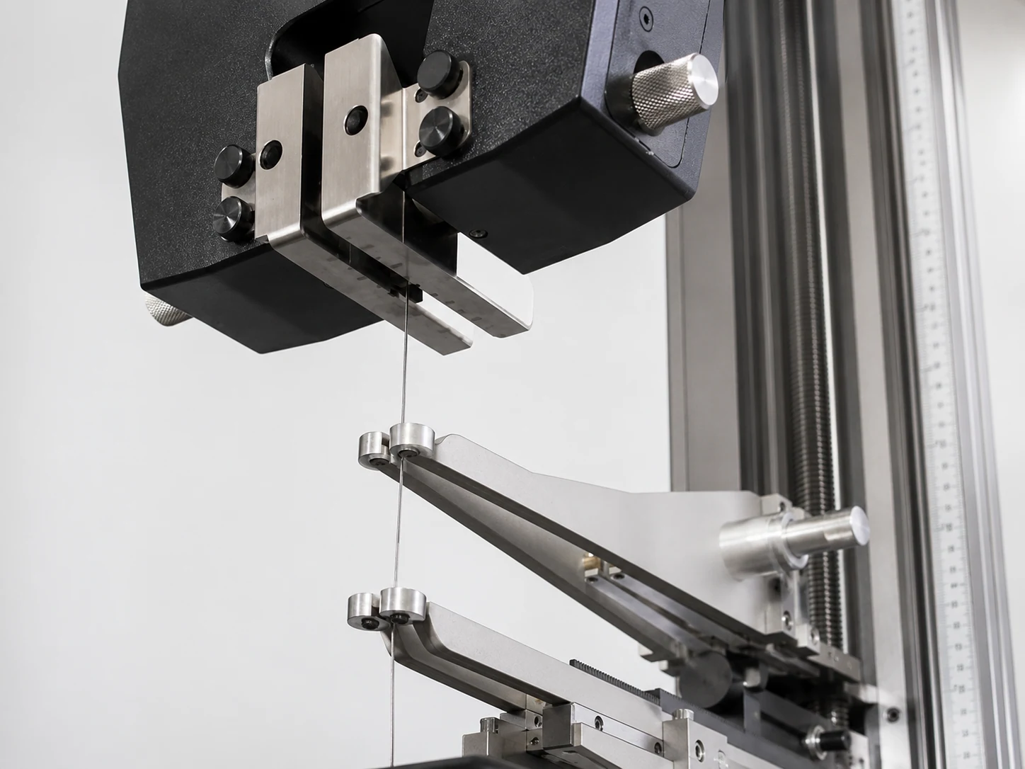
Answers: does the part meet the project load, stiffness, fatigue, environment or other functional requirement? Evidence: customer-approved test plan and project-selected test result. Protects: prevents release based on appearance alone when the part still has not proved the load, stiffness or environment that determines whether it remains usable.
 SAMPLE TYPE 04
Process or limited production
Answers: can the released tooling, process, secondary work and inspection produce the approved state beyond one hand-built piece? Evidence: first article, limited batch, process records and agreed sampling or full inspection. Protects: shows whether the approved condition can survive more than one carefully adjusted sample before the buyer commits to a larger order.
Project example: the first sample set was not approved
An industrial-equipment housing program started with five compression-molded samples. The sample set had to prove an agreed visible surface and flange geometry. NEXWAVE did not ask the customer to accept the parts as "close enough."
First set of five fails inspection
Inspection found visible pinholes and two flanges at 0.25 mm flatness against the 0.15 mm project requirement.
Second round, controlled changes
Lower-viscosity resin direction · molding pressure 80 → 100 bar · hold time 5 → 8 min · tool repolished to below Ra 0.4 μm · 100% flange-gauge checks. These are the settings for this project, not a general molding recipe.
Second set of five passed
The customer approved the FAI package and the retained Approved Sample.
The buyer avoided sending a flange problem into a sealed assembly and a pinhole problem into a later paint process, where the same defects would have meant disassembly, refinishing or replacement instead of one controlled sample correction.
Contain Nonconforming Carbon Fiber Parts Before They Affect the Whole Order
When a defect appears in production, the first useful answer is not "we are investigating." It is: Which parts are affected, where are they now, what will happen to them and what must change before production continues?
Without an affected-scope check, the factory has two bad choices: ship parts that may share the same cause, or hold and sort far more of the order than the evidence supports. Material lot, tool, cure batch, bagging, operator and inspection records help identify which parts passed through the same conditions. That allows a three-part problem to remain a three-part problem when the records support it. When they do not, containment must widen.
NEXWAVE separates an actual nonconformance from a planned engineering change. A nonconforming part is detected, stopped and isolated. The affected scope is checked against material, tool, process and batch records. The disposition may be rework, repair, customer-approved concession or scrap. Root cause, corrective action and the required verification are closed before the approved production basis continues.
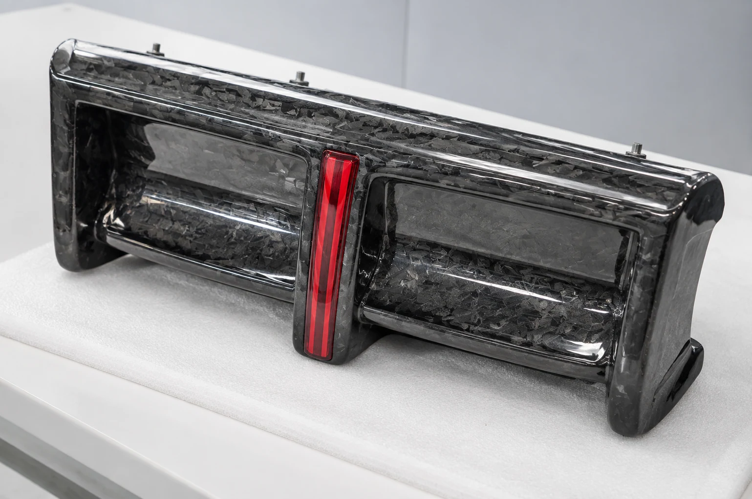 FIG 6.A · D65 VISUAL GATE
The records showed why the affected population was three parts instead of an unsupported assumption about the whole order. That kept known defects out of the customer's paint and assembly process while preserving the acceptable parts and the delivery recovery plan.
Move From an Approved Sample to Repeat Carbon Fiber Production
One experienced technician can make an excellent sample by compensating in ways that never appear on the drawing: shifting a ply around a tight corner, adding pressure by hand, trimming to a mating part or polishing one surface until it looks right.
The sample can pass even though another operator, another material batch or the first production fixture will not repeat those corrections. Repeat production begins only when the reasons the sample passed are transferred into materials, tooling, work instructions, secondary operations, inspection and change control.
Material controls reduce unapproved fiber, resin or batch variation. Tools and fixtures locate the shape and features without relying on hand adjustment. Work instructions and machine programs turn the technician's successful method into repeatable steps. Inspection catches drift before shipment, while the retained sample and approval record give both sides the same comparison point. Without that transfer, the Approved Sample proves that one part succeeded. It does not prove that the next order can reproduce it.
The released part revision, material source or batch range, laminate traveler, tool and fixtures, cure program, CNC program, bonding or insert method, appearance reference, inspection plan, packing state and retained sample. The exact set follows the product and the risk.
Project example: five approved samples did not prevent first-batch drift
Five autoclave-cured automotive interior samples passed customer FAI. In the first 50-piece production batch, the customer measured three parts at 85–88 GU against a project requirement of at least 90 GU; the other measured parts were in the 92–95 GU range.
NEXWAVE paused the finishing operation for two days, checked all 50 parts, refinished the three low-gloss parts and submitted five revised samples for approval. The production basis then locked the clear-coat source and batch range, spray-fixture angle and spacing, an 80°C × 60-minute project cure followed by at least four hours of natural cooling, and the gloss inspection plan.
Gloss units · first 50-piece batch · three markers below the requirement line
What triggers another review
Define the Finished Carbon Fiber Part You Need Delivered
"Carbon fiber part" can mean a molded shell, a CNC-finished component, a bonded assembly or a branded product packed for export. If the delivered state is vague, a low part price can hide the machining, hardware, finishing, inspection, packing and transport work still waiting for the buyer.
Every outside handoff adds another queue, packing step, shipment and tolerance interface. A second supplier may receive the molded part without the same datums or inspection basis, and the buyer may not know whether a bad hole came from molding, machining or insert installation. Even one omitted operation can hold the full product when all other components are ready.
Comparing the finished delivered state therefore changes both the true project cost and whether the order can move directly into the customer's retained assembly work. NEXWAVE connects the included operations to one finished-part definition. The customer still controls the product and approval decisions assigned to them, but the quoted supplier scope says exactly what arrives.
Project example: from a frame blank to a part ready for system assembly
Packing list · every line checked before release
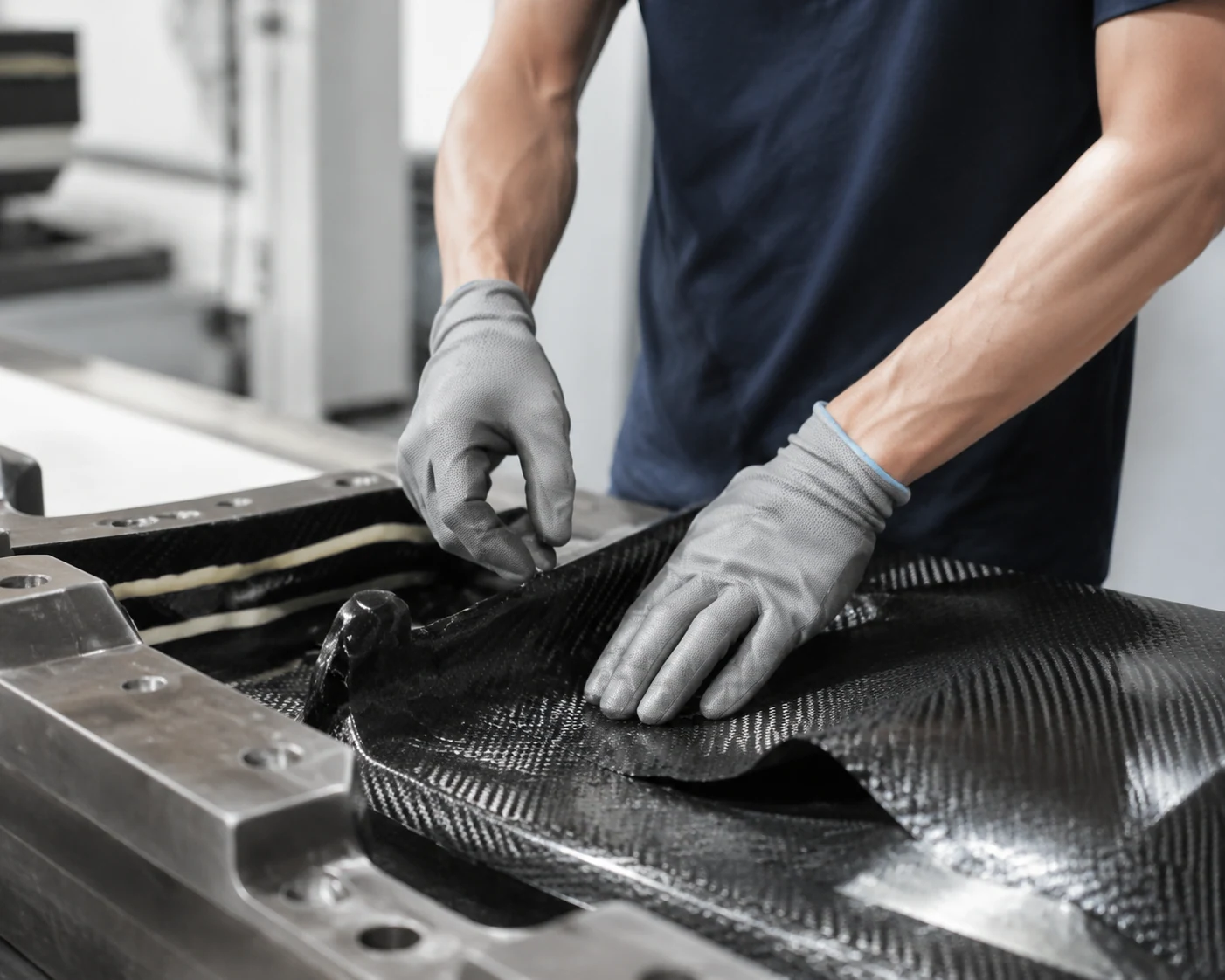
Prepreg layup and autoclave cure
Released material/process records for the project
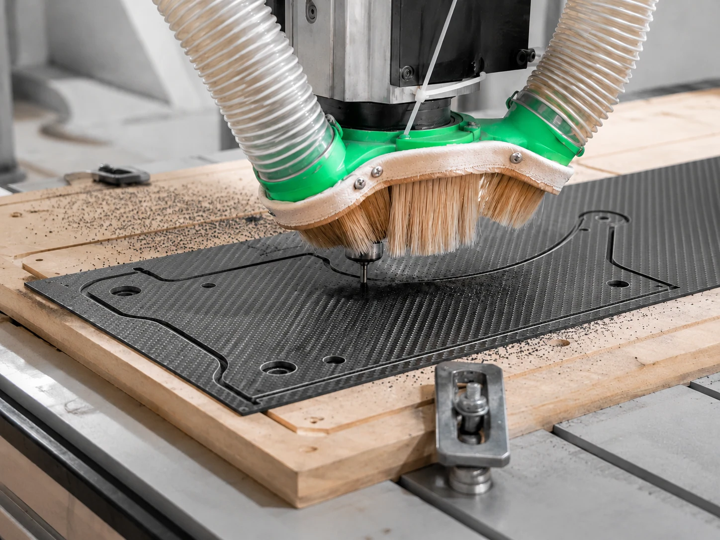
CNC profile and hole machining
CMM from three datum holes plus go/no-go gauge records
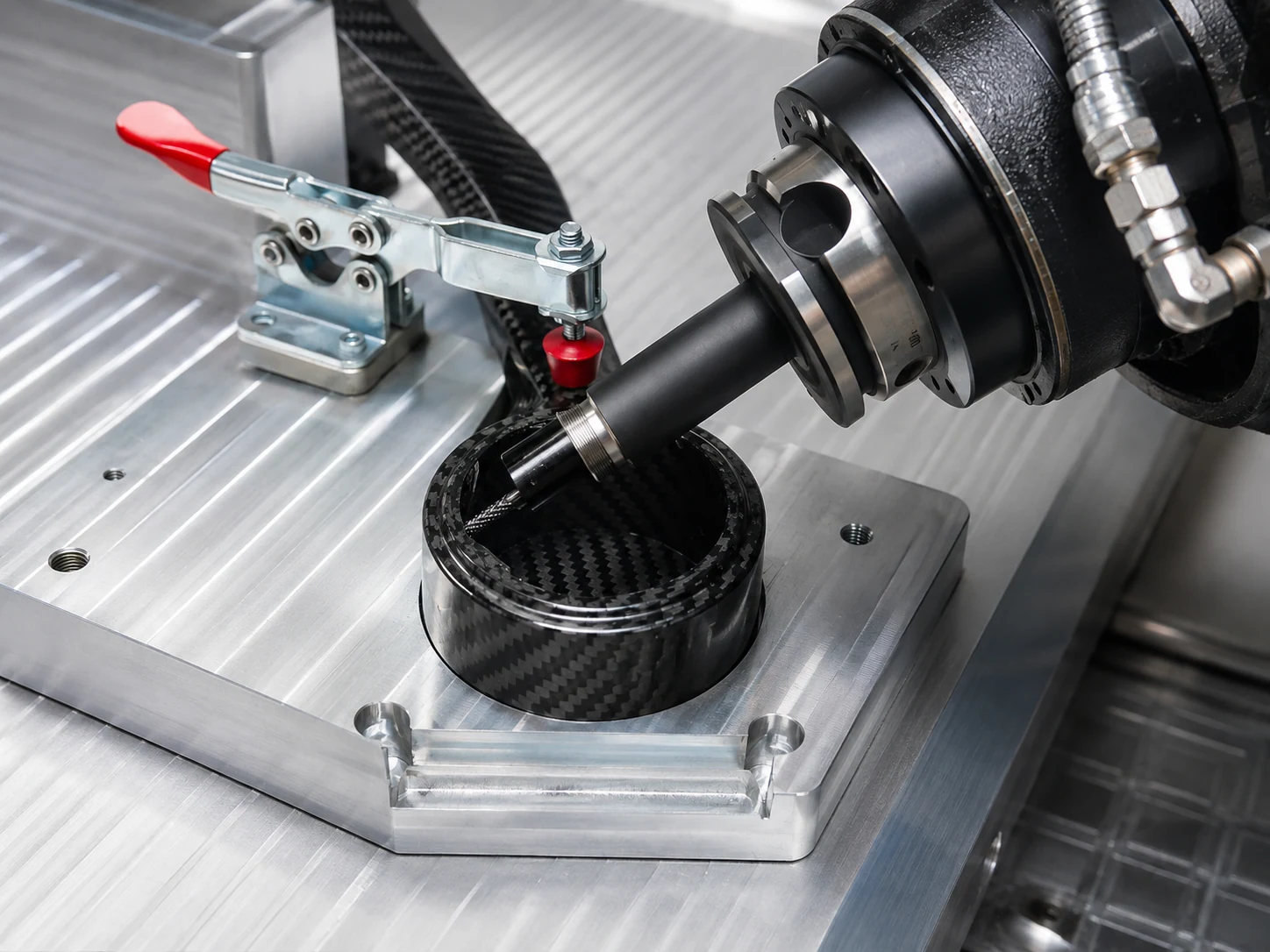
Installation of eight M3 threaded inserts
Insert-torque record at the project requirement of 0.8–1.2 N·m
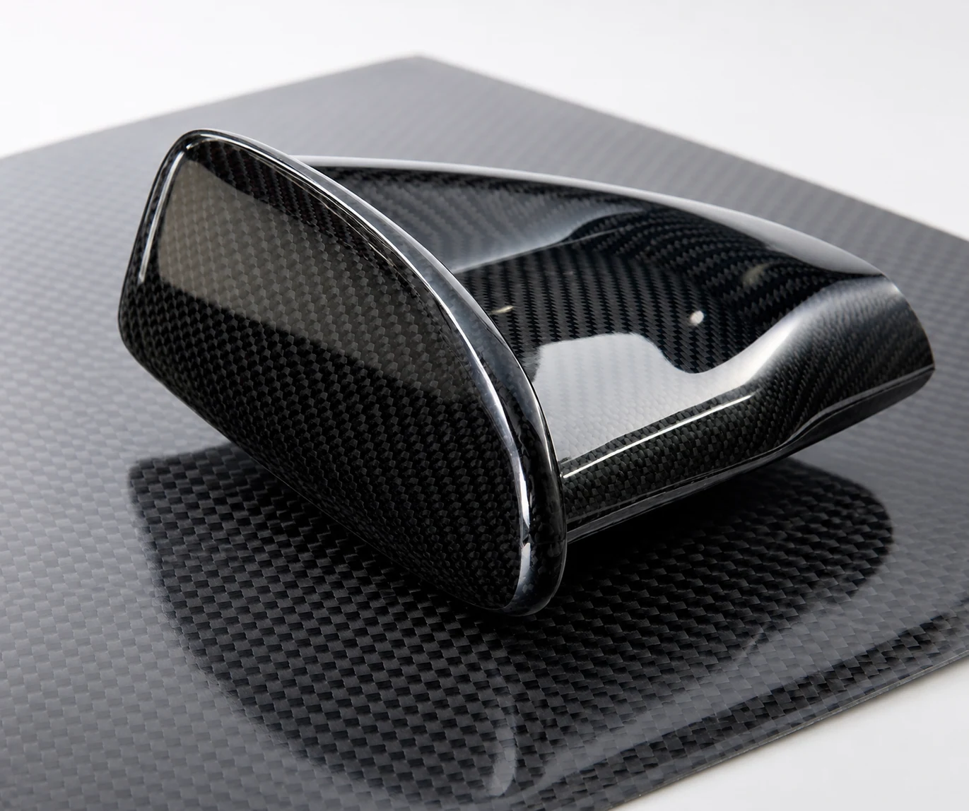
High-gloss clear coat and laser-engraved logo
D65 visual and gloss checks against the approved state
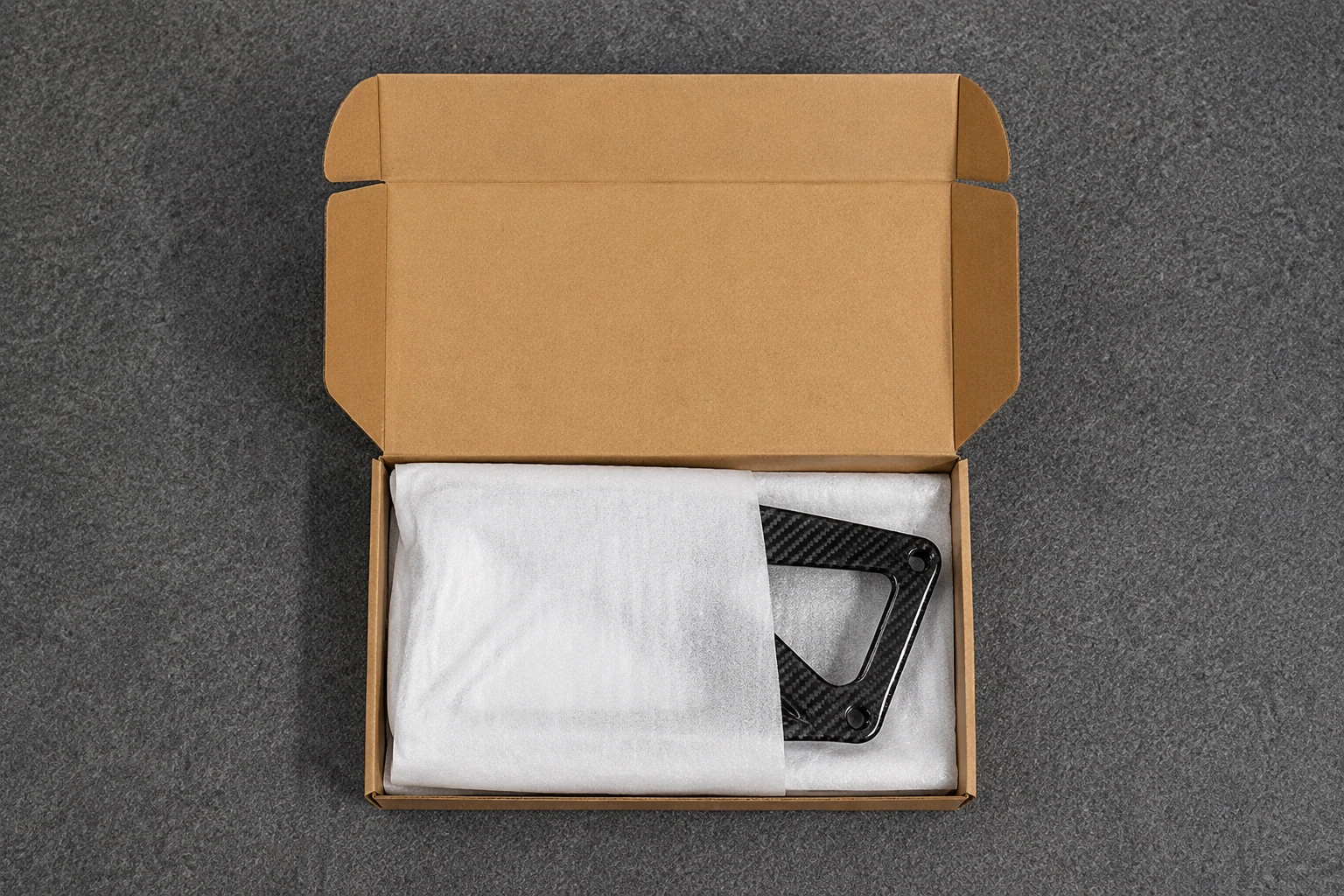
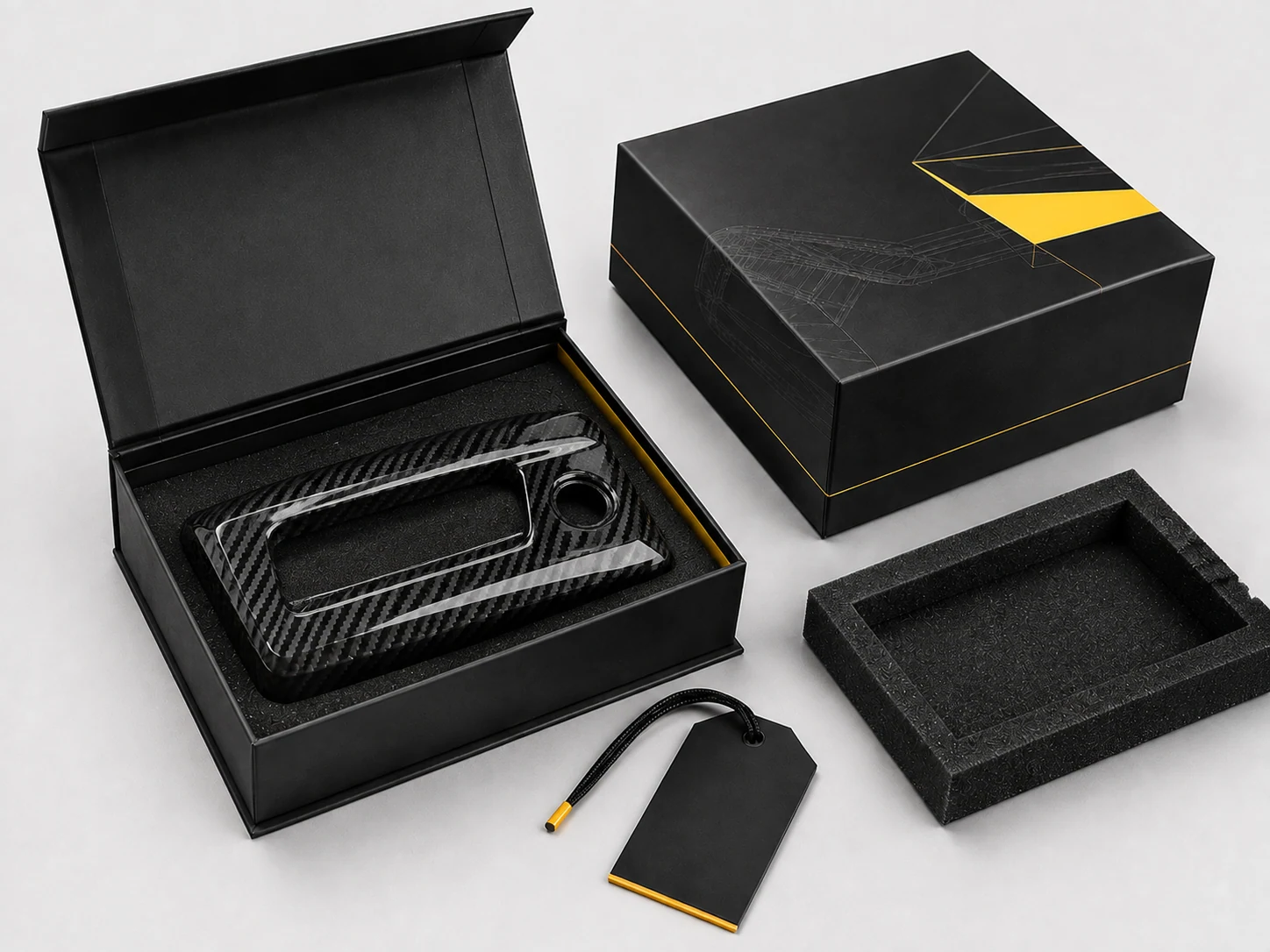
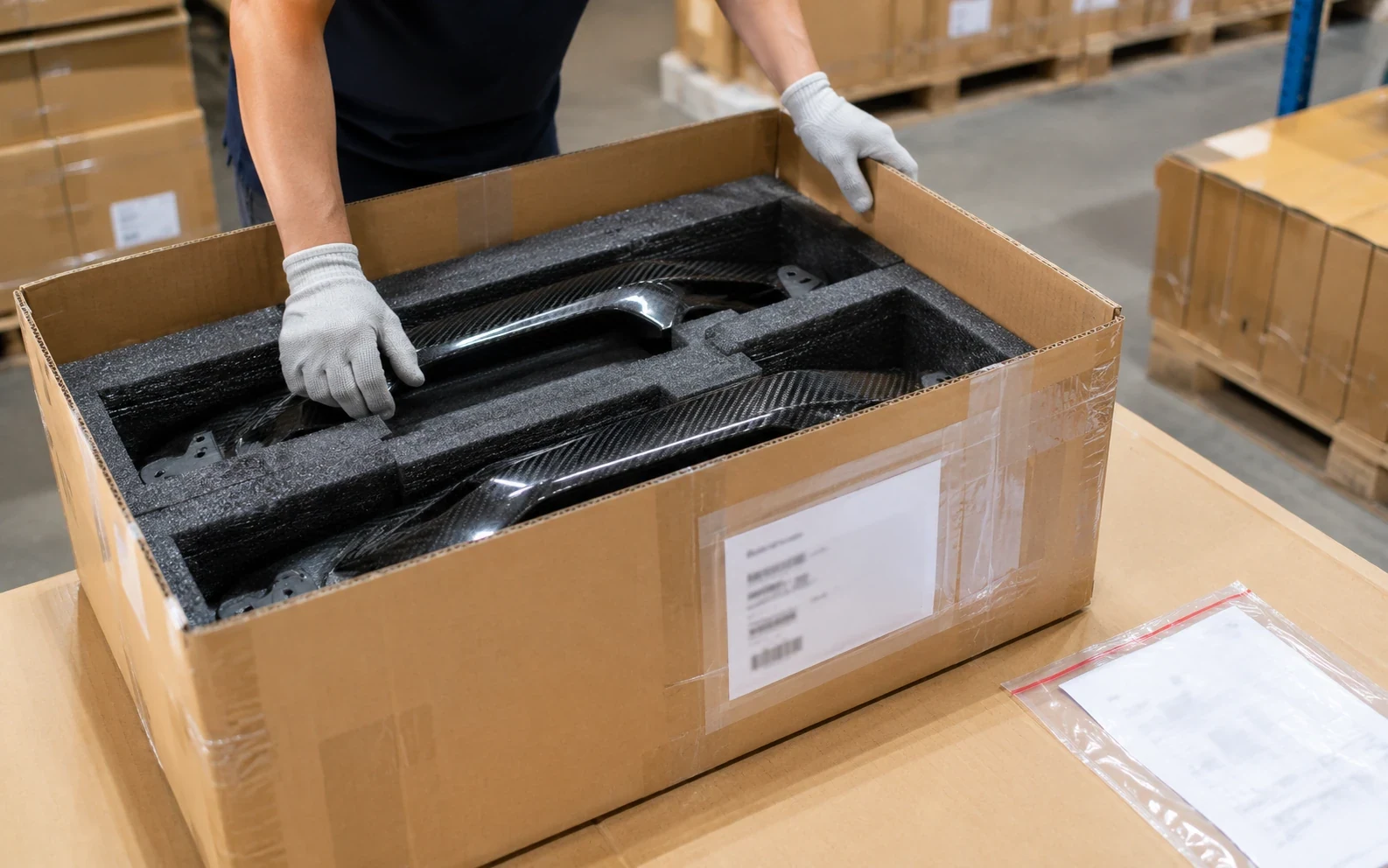
Shaped antistatic foam tray, moisture-protection bag, five-layer carton, export pallet and documents
Packing checklist and confirmed shipment state
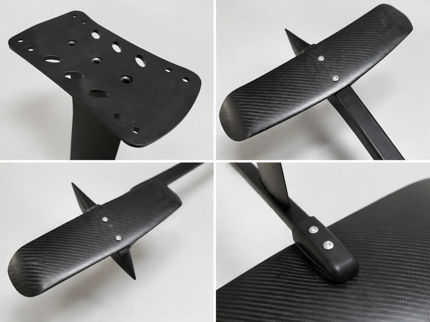
Final system assembly and installation
Customer-controlled system integration
Against the buyer's original plan to send the received plates to separate CNC and insert suppliers, the integrated route removed one outside operation and one transport handoff. For this order basis, it saved 5–7 days per batch and 2–3 weeks of the buyer's internal downstream work. Those times belong to this comparison; they are not a standard lead-time promise.
The buyer received the holes, inserts, finish, brand and packing that the assembly expected. One missing secondary operation no longer had to hold the entire product while another supplier was found.
Protect OEM/ODM IP, Tooling and Brand Decisions
Commercial control continues after the engineering works. Buyers still need to know who can access the files, which revision reaches production, how customer-funded tools are maintained and who approves the brand that reaches the market.
Those controls affect physical output. An obsolete drawing can put an old hole pattern or laminate into a new batch. Unrecorded tool wear can move a flange or degrade a visible surface. An unapproved label or package can make an otherwise acceptable product impossible to release under the customer's brand. File, tool and brand control therefore protect the reorder from becoming a technically good part built to the wrong commercial definition.
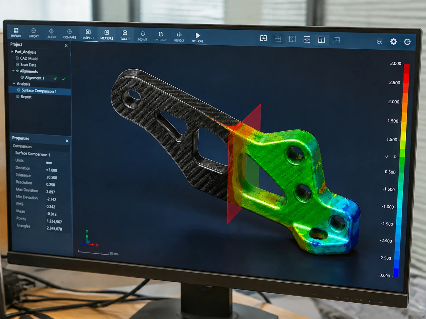 FILE 9.1 · REVISION
Keep the released revision in production
NEXWAVE receives project files through controlled email or the company file service and separates them by project. File names carry the project, part, revision, date and format. Engineering and the project manager manage the working data; production accesses the released folder rather than every historical file.
When a drawing changes, the ECN carries the customer approval. Obsolete controlled copies are withdrawn and the current shop-floor copy is marked as controlled. This reduces the chance of a tool, CNC program, inspection plan or batch being built from the wrong revision.
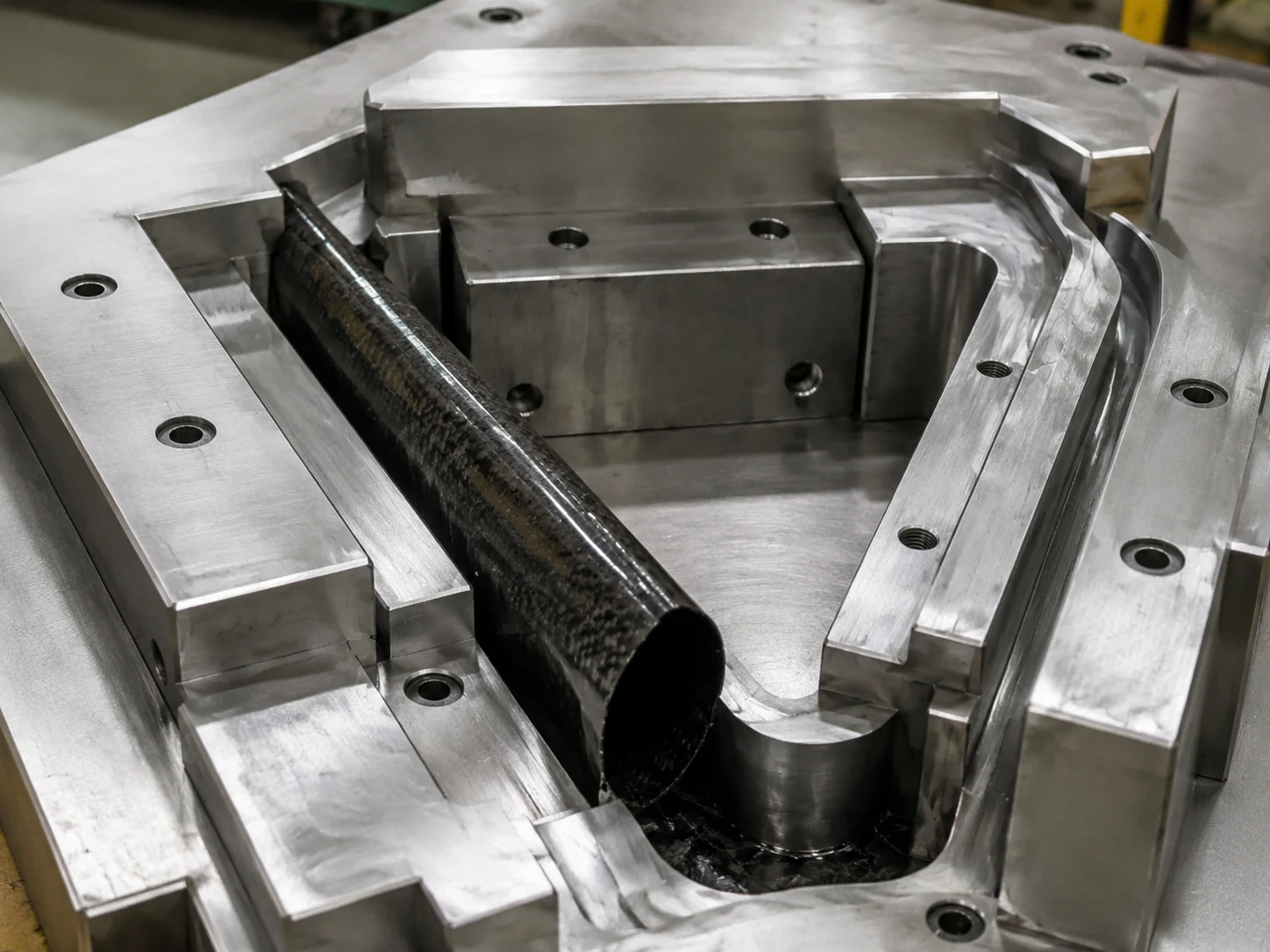 FILE 9.2 · TOOLING
Treat customer-funded tooling as a project asset
Customer tools are identified and recorded with the tool drawing, material/acceptance information, use count and maintenance history. Storage, maintenance, major repair, permitted use, transfer and end-of-program disposition follow the signed agreement.
In one automotive roof program, a customer-funded steel tool showed about 0.05 mm of parting-line wear after roughly 300 uses. The parting surface was reground and polished over three days, and the first part after maintenance passed CMM inspection. The case shows why tool condition and post-maintenance verification belong to repeat supply; it does not create a universal maintenance interval or cost.
 FILE 9.3 · BRAND
Keep brand approval with the customer
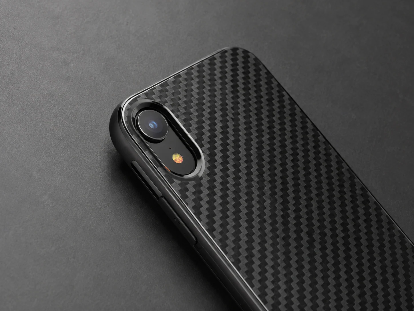
NEXWAVE can execute quoted screen printing, laser marking, customer-specified colour and approved branded packing. ODM and private-label work may also include artwork or label-development coordination. The customer still owns the logo and brand assets, label content, packaging artwork and final brand approval.
IP ownership, design-output ownership, exclusivity, price-lock periods, tooling transfer and confidentiality obligations depend on the project agreement. The page can explain what to settle; it cannot replace the contract.
 VISA PAGES · THREE STAMPED PROJECTS
See How NEXWAVE Solves Real Carbon Fiber OEM/ODM Problems
Equipment lists show what a factory owns. Project records show whether the team can connect a customer's problem to engineering, manufacturing, verification and repeat supply. These three projects cover different reasons buyers seek OEM carbon fiber solutions.
 RECORD 01 · AUTOMOTIVE FIT
Stop asking the installer to fix the part
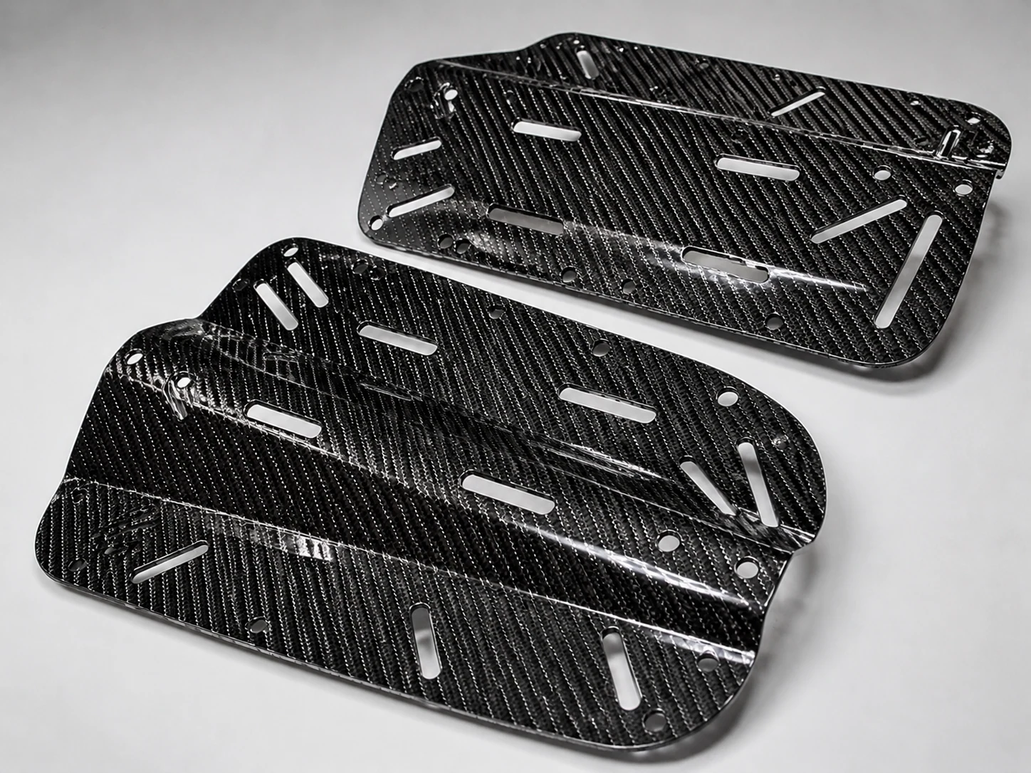
A BMW E46 foot-tray project started after the customer reported a same-platform supplied-state part above 950 g that required about 2–3 mm of trimming. NEXWAVE developed a project-specific quasi-isotropic T700-twill and local T800-UD prepreg route, autoclave cure and 3D CNC finishing. The finished part passed CMM and installed-fit checks, moved through a 10-piece pilot and entered repeat production reported at 50–100 pieces per month.
For this project, laminate, tool, CNC contour and installed-state verification were solved as one part problem. The result is not a universal fit or weight promise.
 RECORD 02 · INDUSTRIAL UAV
Do not buy a separate molding assumption for every shape
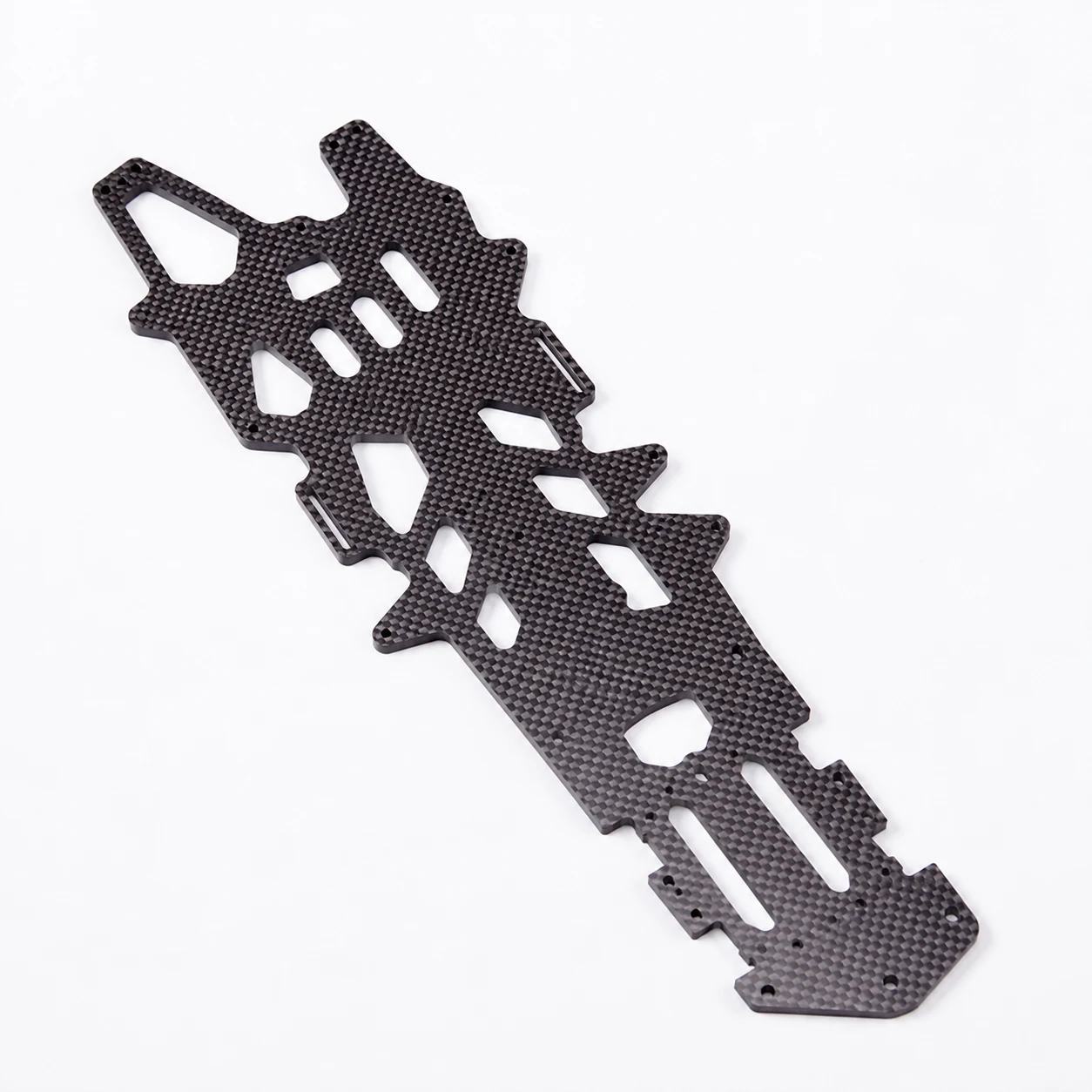
An industrial UAV program covered 21 released frame-plate variants based on three platform configurations and seven load configurations. A representative 180 × 180 × 2.0 mm, 50-piece plate used the plate-and-CNC route. A four-part vacuum fixture reduced the recorded complete machining cycle from 15 to 5 minutes for that configuration. Across the released family, the six-month delivered average was about 550 pieces per month.
These figures belong to that plate family, fixture, features and period. The transferable point is the decision: changing variants and machined features were handled through one route designed around the family rather than a vague promise to "scale."
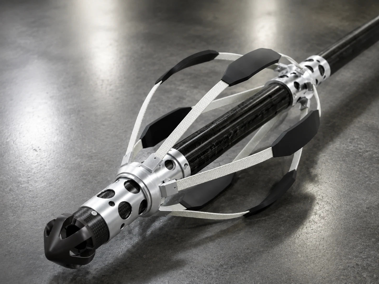 RECORD 03 · ROBOTICS
Reduce mass without losing the defined load path
A robotic end-effector support replaced a creeping carbon-filled-nylon print and a same-function 2.4 kg aluminum route. NEXWAVE used an autoclave-cured sandwich construction, local 0° UD reinforcement and CNC-finished interfaces. One specimen passed the project's defined one-million-cycle laboratory test before formal release of 50 pieces and later repeat orders.
The result applies to the recorded 5 kg and ±50 N load inputs, interface, finish and test conditions. It proves that the product target, laminate, interfaces, test and production release were connected before repeat supply.
Choose a Carbon Fiber OEM Product Program
Use the general OEM/ODM review when the product does not yet fit a defined program or when the first decision is the partnership model. If the product type is already clear, use the closest program to focus the review on its geometry, tooling, finish, validation and market requirements.
A cue shaft, electronics housing and branded carrying case do not fail at the same interfaces or need the same validation. Routing a clear product to its closest program keeps a general OEM/ODM review from overlooking the product-specific feature that determines whether it can be manufactured, approved and sold.
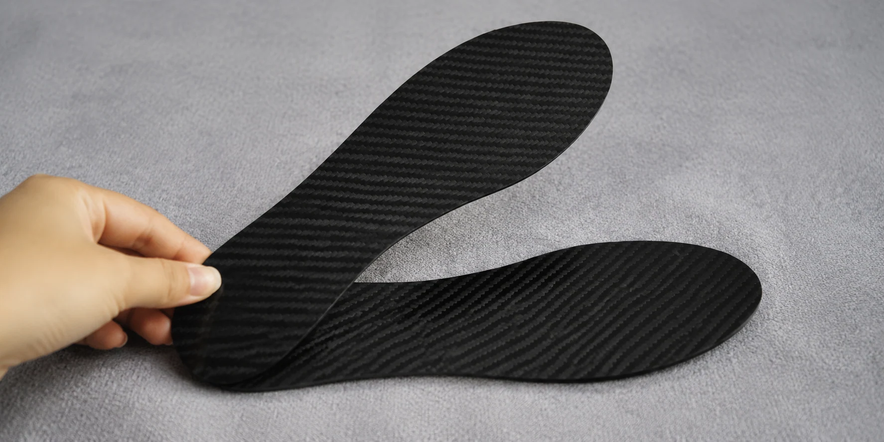
Everyday, home and brand programs
04 DESTINATIONS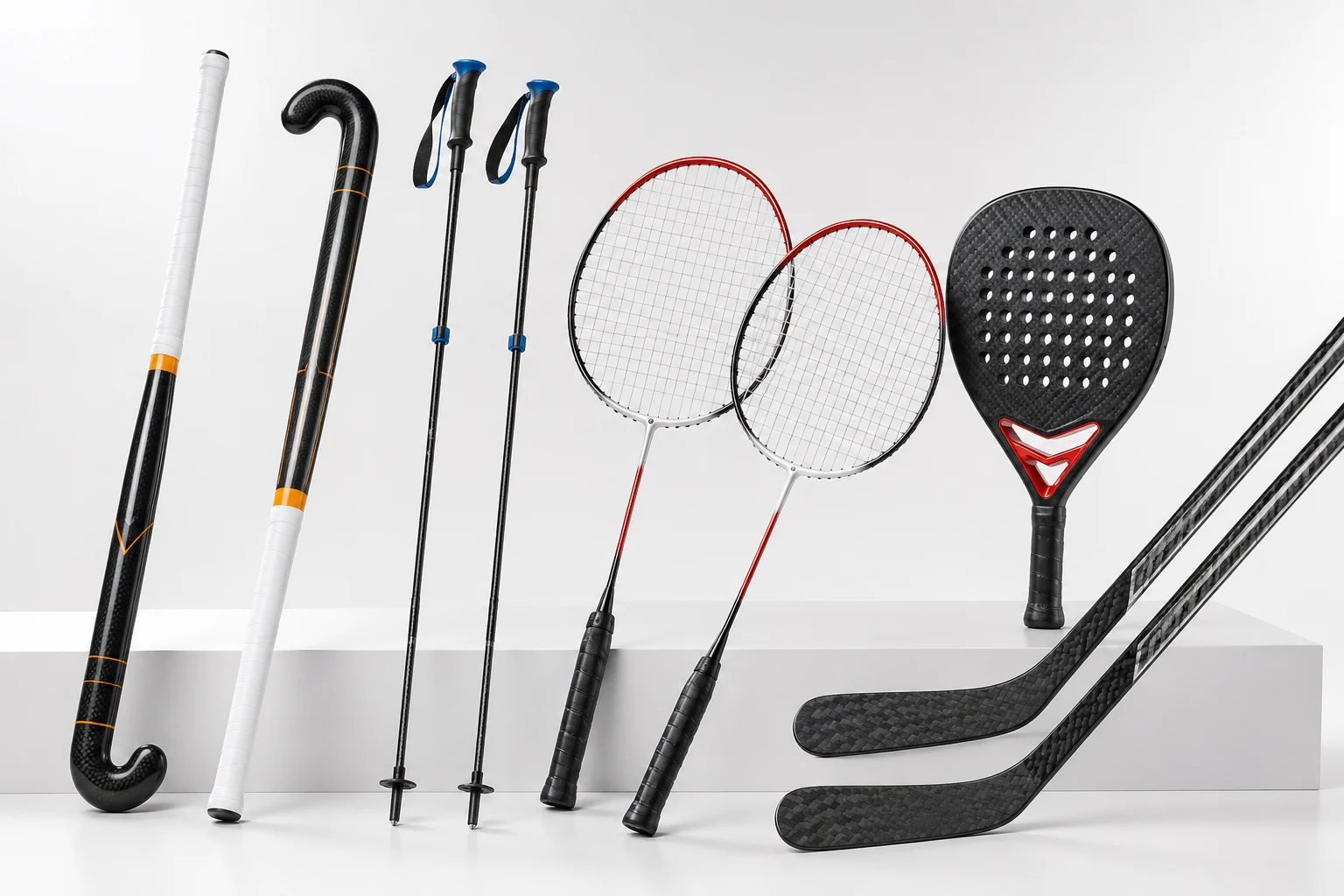
Sports and performance programs
14 DESTINATIONS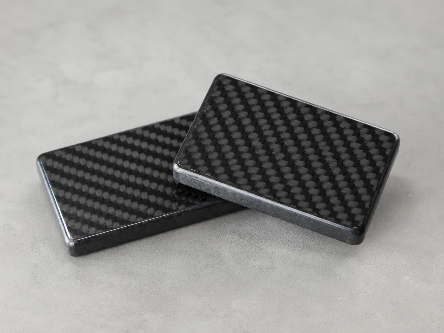
Personal, mobile and lifestyle programs
13 DESTINATIONS
Electronics, audio and mobility programs
03 DESTINATIONSCarbon Fiber OEM/ODM Questions That Still Affect the Route
Yes. A sample, photographs and known dimensions can support an initial route review. If production depends on hidden surfaces, interfaces or controlled geometry, scanning, reverse engineering or new CAD may need to be defined as project work before tooling.
A new tool is usually required when the intended geometry, surface, process and production state cannot be proved through an existing qualified tool, plate-and-CNC route or appropriate prototype method. The decision follows the product and validation target; a cheap prototype route should not be used to approve a surface or dimensional result it cannot reproduce.
Because it may use a different tool, laminate, process or inspection basis. Approving visible weave and gloss does not approve mounting holes, load capacity, fatigue behaviour or production repeatability unless those items were included and verified.
Yes, if the available data, tool condition, sample basis and ownership rights can be reviewed. NEXWAVE first identifies what the existing sample actually proves and which design, tooling, process or inspection information is missing before deciding what can be retained.
That is settled in the project agreement before protected data or customer-funded tooling is used. The agreement should name the background IP, project outputs, tool identity, custody, permitted use, maintenance, transfer and end-of-program disposition instead of relying on a general website promise.
A preliminary route can be discussed while some details remain open. A reliable quotation needs enough definition of geometry, quantity, tooling, finish, inspection, packing and delivered state to separate one-time work from repeat part cost. An off-the-shelf aftermarket unit price can offer background, but it is not a like-for-like quote for a custom OEM program.
Start With the Carbon Fiber Part Problem You Need Solved
You do not need to write a perfect RFQ before NEXWAVE can look at the project. Send what you already have and name the result that is not yet secure: the part must fit, a weight target must be proved, the sample must survive a specific test, the first batch drifted or the delivered order still needs machining, hardware, finish or packing.
Custody chain closes here · [email protected]
Useful starting information
NEXWAVE will confirm receipt, identify the missing inputs and return a preliminary manufacturing-route recommendation when the available information is sufficient for review. When geometry, tooling, validation, acceptance and delivered scope are defined well enough, the project can move to quotation.