
Custom Carbon Fiber Parts Manufacturing
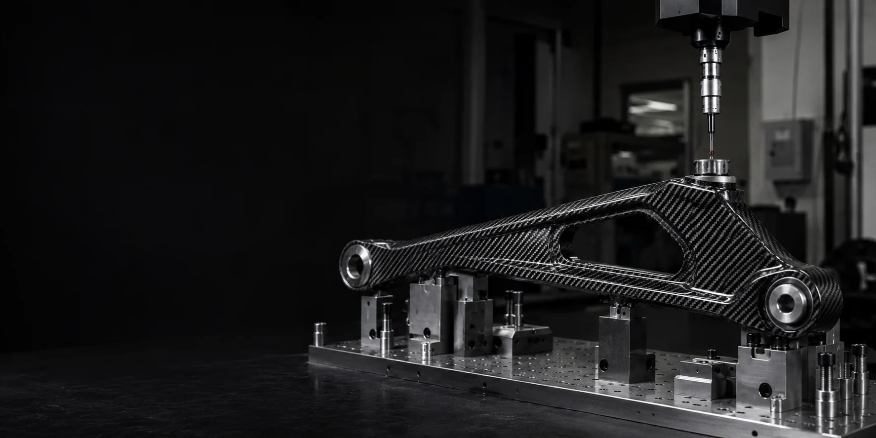
Bring CAD, drawings, a sample, an existing part or the problem you need the part to solve. NEXWAVE develops the route toward a finished carbon fiber component that fits its assembly, performs its job and can be made again.
ENGINEERING → DELIVERY
What a successful custom-partsproject should protect
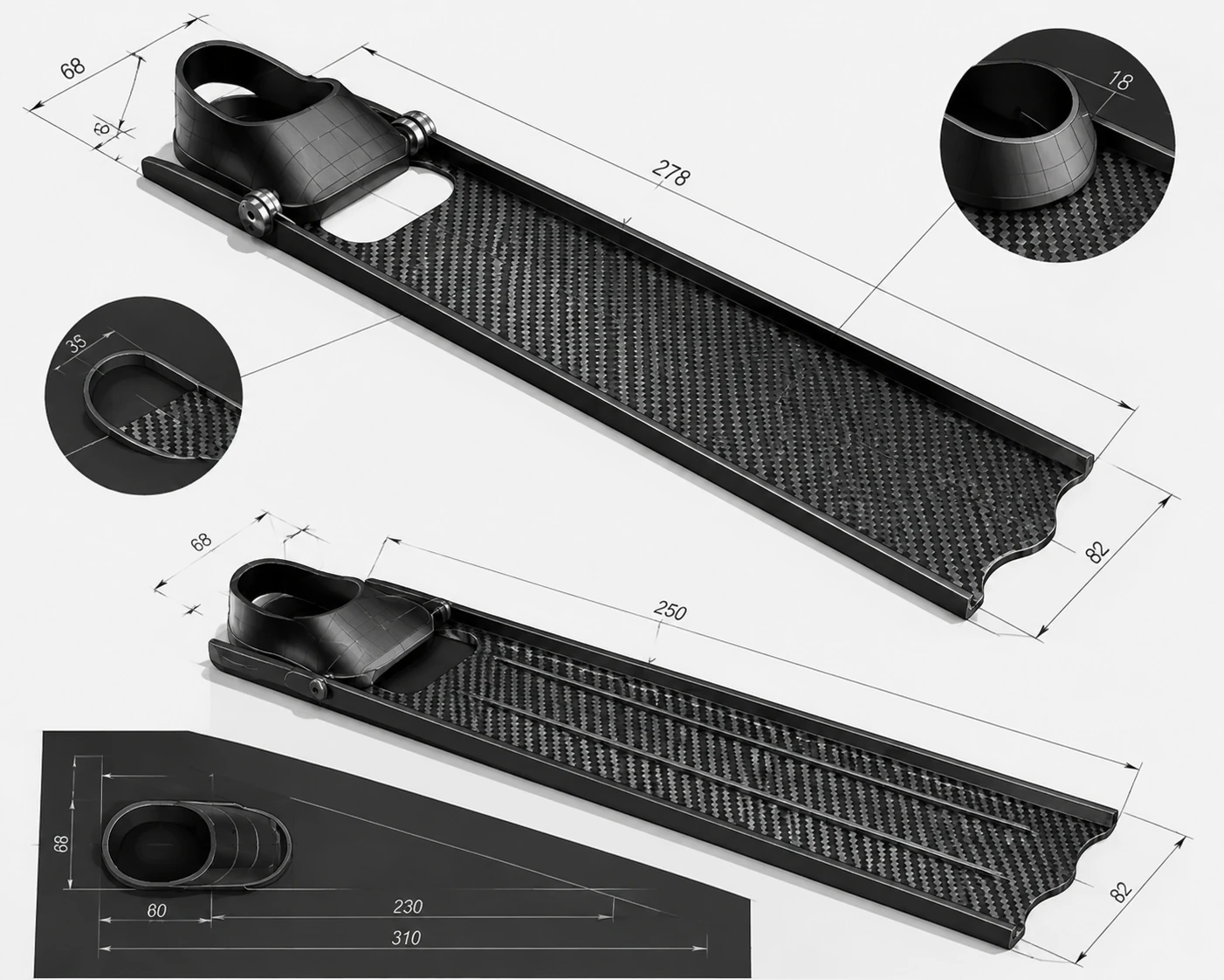
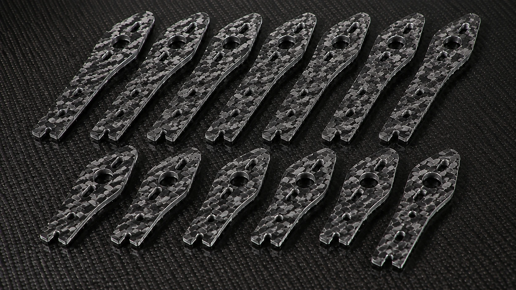
Start with the part and informationyou actually have
Sometimes the starting point is clean CAD and a released drawing. Sometimes it is an old part, a broken sample, photographs, scan data and several files that disagree with one another. The danger is not that the information is incomplete. The danger is treating every input as equally reliable and building the next tool around the wrong one.
NEXWAVE first clarifies what the part must do and what has already gone wrong. The engineering review then checks five practical areas:
That review separates two very different starting states:
Depending on the quoted scope, scanning and measurement may be completed by NEXWAVE or a fixed project partner. NEXWAVE can define the datum plan, review the point cloud or mesh, rebuild surfaces and interfaces, compare the reconstructed geometry with the source part and return controlled STEP data or interface drawings.
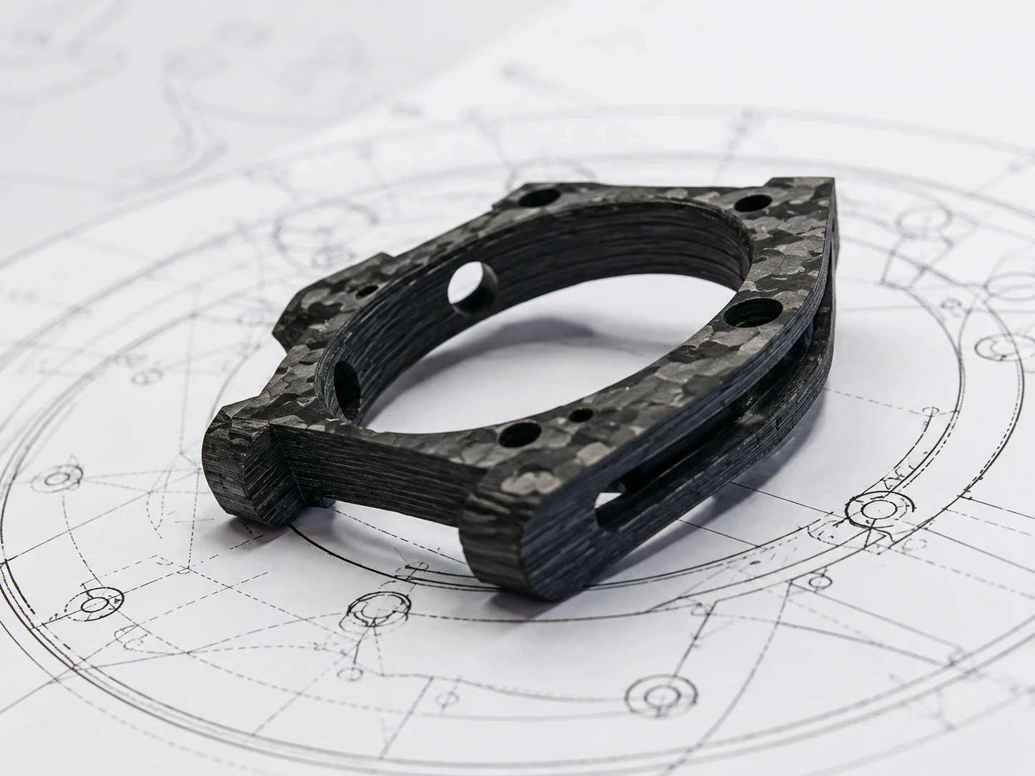
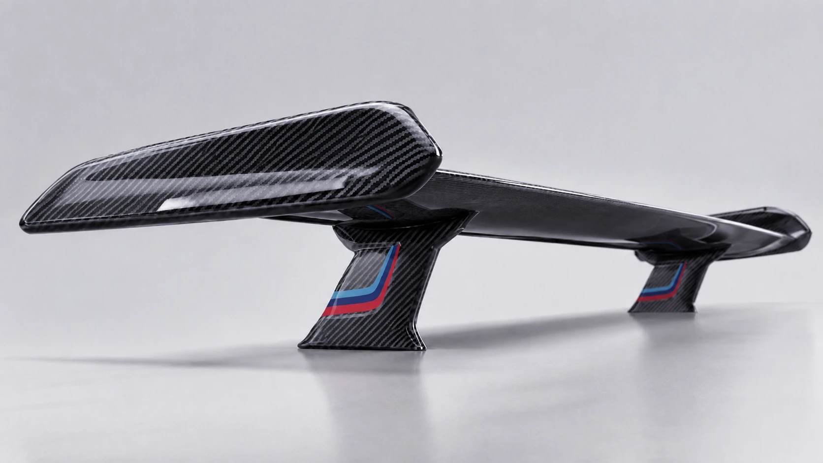
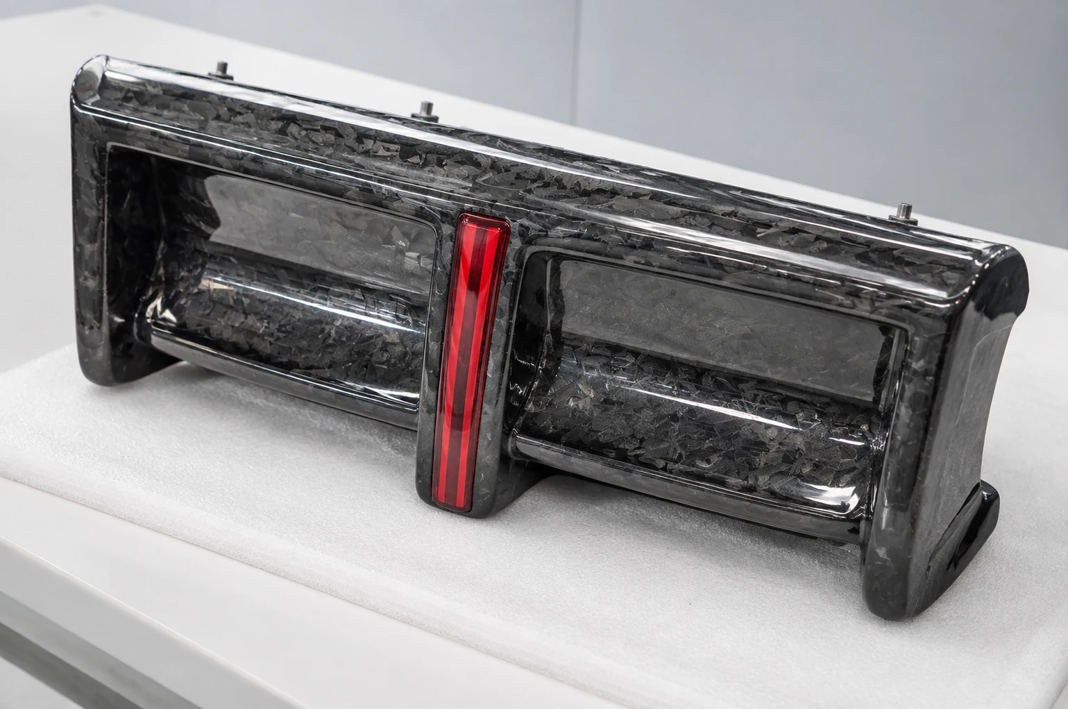
A broken spoiler became a usable engineering starting point
For one anonymous replacement project, the customer had an old spoiler with a broken mounting feature plus photographs. The remaining geometry was scanned, the damaged mount was reconstructed from the symmetrical side, and the mounting relationship was checked before DFM. The customer received STEP data, a 2D interface drawing and mounting confirmation. The recovery took about two weeks for that project.
The useful result was not simply a new file. The next engineering decision was based on a defined mounting relationship instead of copying damage or guessing at the missing feature.
Engineer the carbon fiber partfor its real job
A metal, plastic or printed part cannot be converted to carbon fiber by copying its outside shape and choosing an attractive weave.
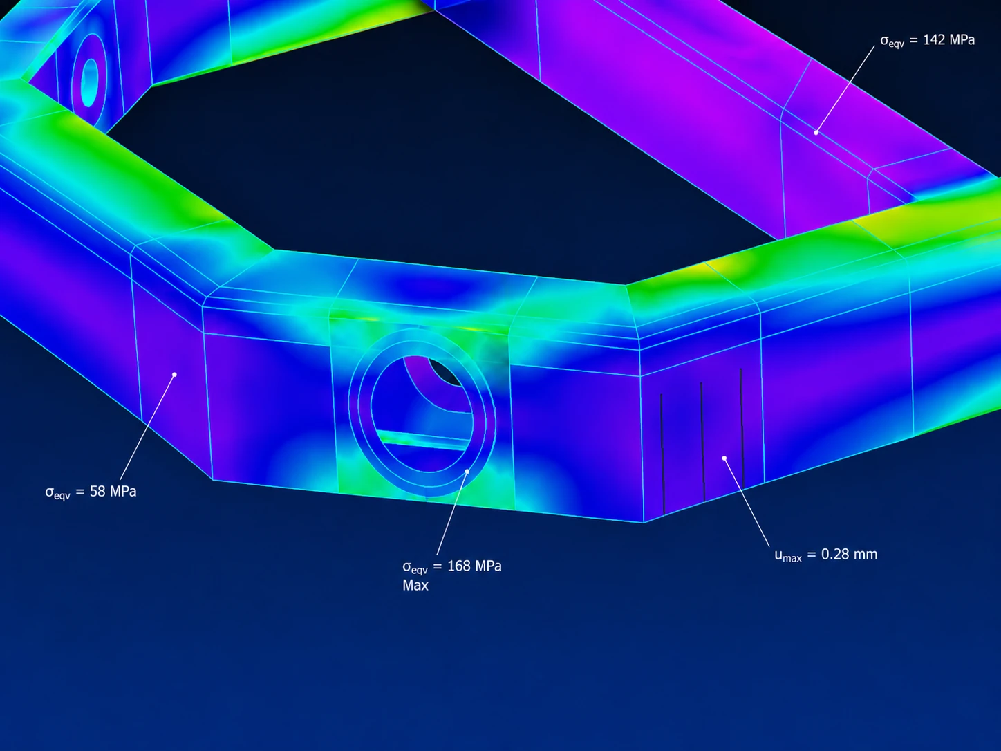
The old geometry may carry load through thick walls, metal ribs or flexible material behavior that does not translate to a laminated composite. If those assumptions remain hidden, the new part can be lighter and still be too soft, weak around a fastener or difficult to validate.
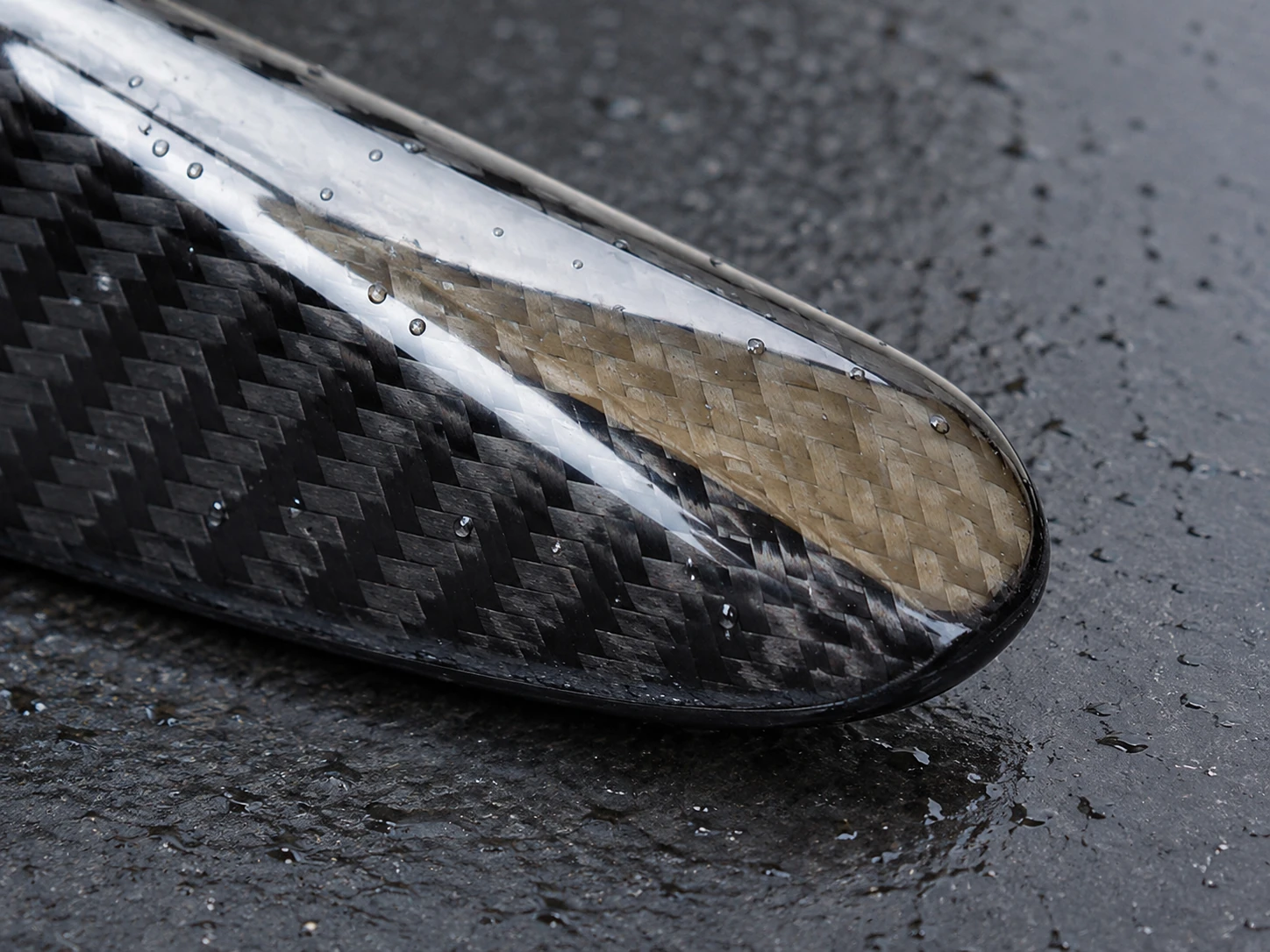
NEXWAVE starts with the job of the component. Depending on the engineering scope, that can include:
Mass estimates, analysis and part-specific testing are added when they are needed and included.
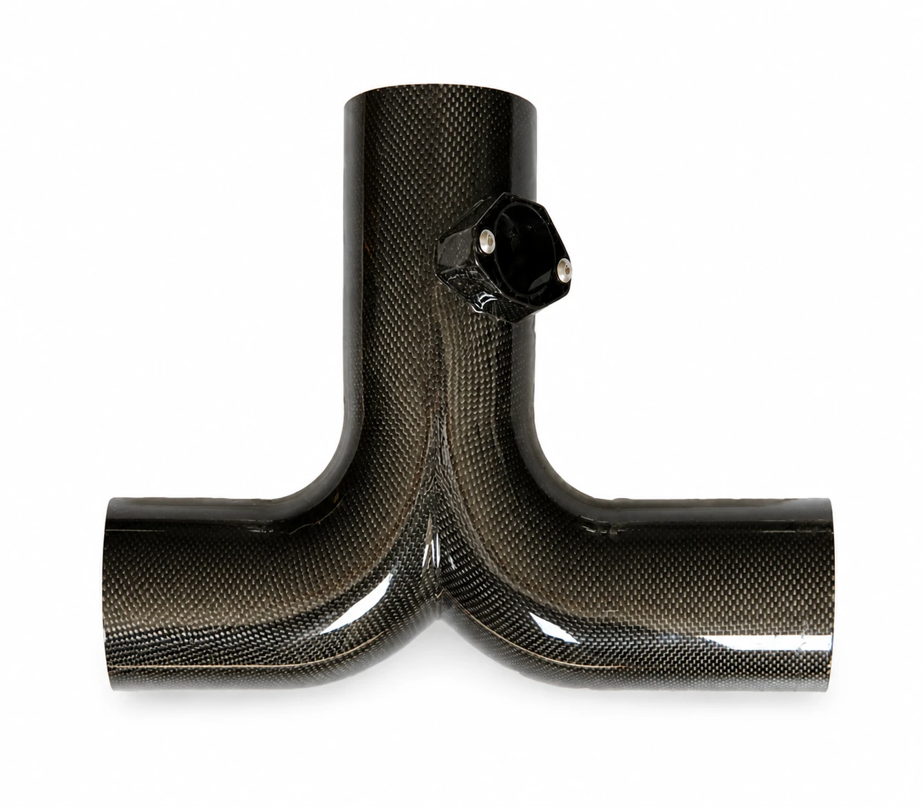
What this changes in the finished part
The engineering work connects fiber direction, core, local reinforcement and interfaces to the part’s actual load path. That helps avoid a familiar failure: an expensive carbon fiber replacement that looks complete but still creeps, moves at its mounting face or misses the weight target because the old structure was copied instead of re-engineered.
In an anonymous robotic end-effector project, a carbon-filled-nylon print had developed creep and the same-function aluminum route weighed about 2.4 kg. NEXWAVE used the recorded 5 kg and ±50 N load inputs in FEA, selected an autoclave-cured sandwich construction, added local 0° UD reinforcement and CNC-finished the mounting interface. The completed carbon fiber assembly weighed 1.15 kg in the same supplied state. Its interface met the project ±0.05 mm CMM requirement, and one specimen passed the defined 1,000,000-cycle laboratory test before formal release of a 50-piece batch and later repeat orders.
Fix manufacturability before it becomesa tool or sample problem
A CAD model can be geometrically complete and still be a poor composite part. A deep wall can trap the tool.
A tight internal corner can make the layup bridge instead of compact.
A trim boundary can be impossible to reach.
A hole or insert can sit too close to an edge for the local structure to carry its load. None of those problems becomes cheaper after the mold is finished.
Composite DFM is where NEXWAVE turns those risks into decisions. The customer-visible output may be an annotated 3D view, marked drawing, issue list, formal DFM report, revised CAD model, tooling concept or open-item register. The format can change with the project, but each useful item should make five things clear:
The review looks beyond generic injection-molding rules. It considers:
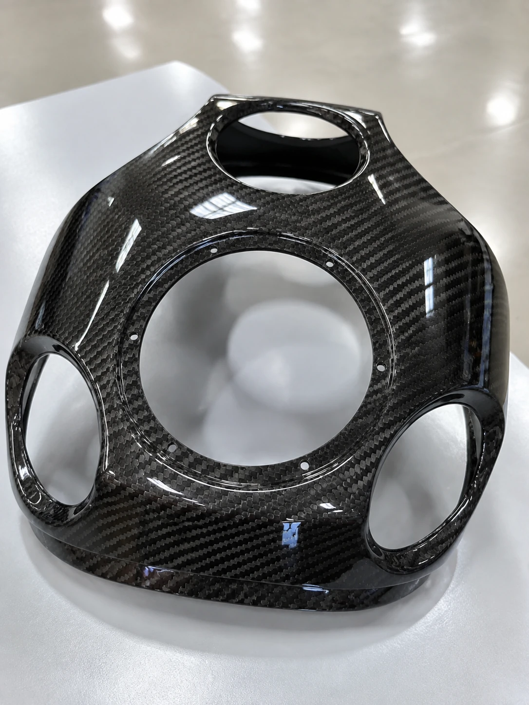
A deep housing needed a different tool concept
In an anonymous industrial-housing review, the starting geometry had a cavity roughly 200 mm deep, R1 internal transitions and a one-piece tool concept. NEXWAVE recommended R5 transitions and a two-part tool so the geometry could be laid up and released more reliably. The customer approved the revised CAD before the tool was made.
This is the point of DFM: a problem that existed as a radius and tool decision was corrected while it was still editable. It does show the customer what a useful review should change before money is locked into hardware.
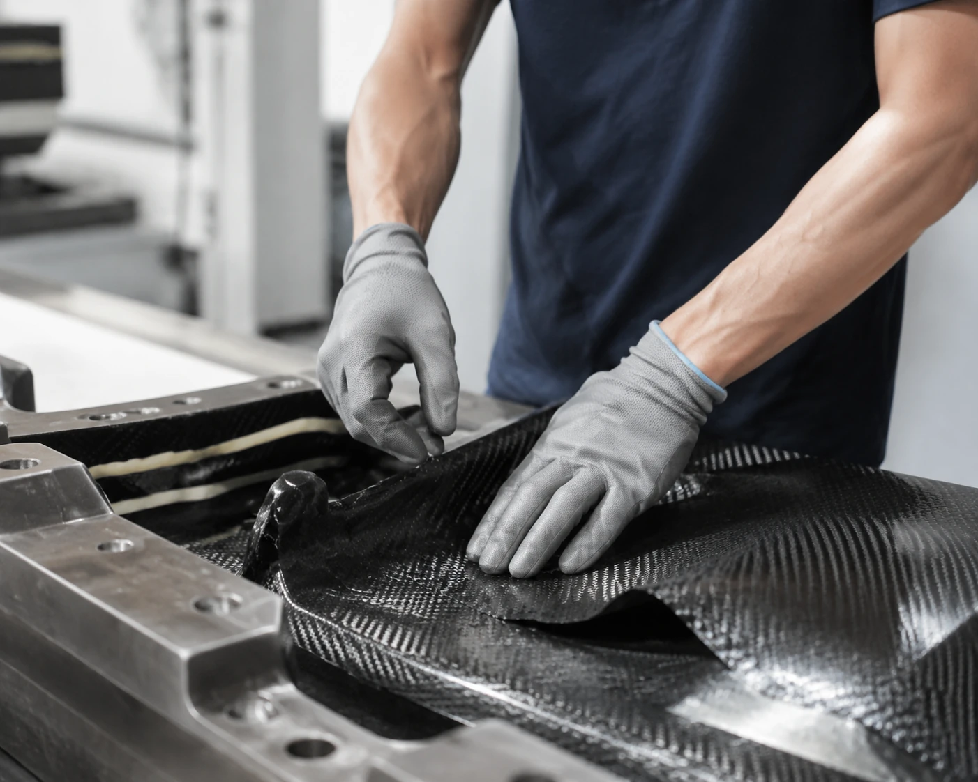
Choose the manufacturing architecture forthe part, variants and order
The most advanced-sounding process is not automatically the right process. A flat precision plate with 21 variants, a deep visible shell and a bonded sandwich assembly do not need the same combination of material, forming, tooling, machining and inspection.
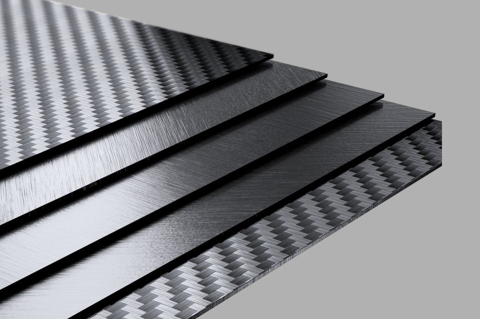
NEXWAVE compares the route around the component rather than around a process label. Candidate routes can include prepreg and autoclave curing, compression molding, vacuum-bag and oven processing, VARTM, wet layup with vacuum bagging, cured carbon fiber plate plus CNC and hybrid forming, machining and assembly.
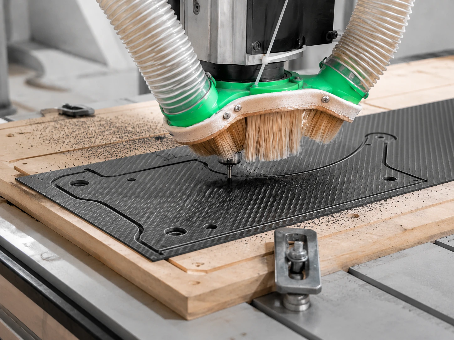
Cured plate plus CNC is often worth evaluating when the part is predominantly planar, multiple variants share the same material and thickness basis, and hole or profile changes would otherwise require repeated tooling. Forming tooling becomes necessary when the product needs a three-dimensional molded surface, controlled appearance or molded structural features. A prototype tool should not silently become the production tool if its material, stability, surface, life or process compatibility cannot reproduce the accepted part.
For a custom part with complex or changing laminate schedules, large or deeply curved molded geometry, an appearance-critical molded surface, or project-specific internal-state and cure evidence, prepreg + autoclave curing can be a candidate.
Controlled prepreg material, vacuum bagging, a defined heat-pressure-vacuum program and its run record work together to support laminate consolidation, surface condition and the approved manufacturing baseline. NEXWAVE considers the route only after checking the usable work zone for the complete part-and-tool load, drape and layup access, vacuum sealing, tool thermal behavior, the required bag-side surface and project acceptance requirements. That early check helps avoid discovering after tooling or sampling that the load will not fit, the laminate cannot be placed reliably, the bag-side surface is unacceptable or the inspection plan cannot prove the required result. The dedicated Autoclave Curing page covers the full equipment, working-zone, program-control and inspection detail.
The choice changes when any of these conditions changes:
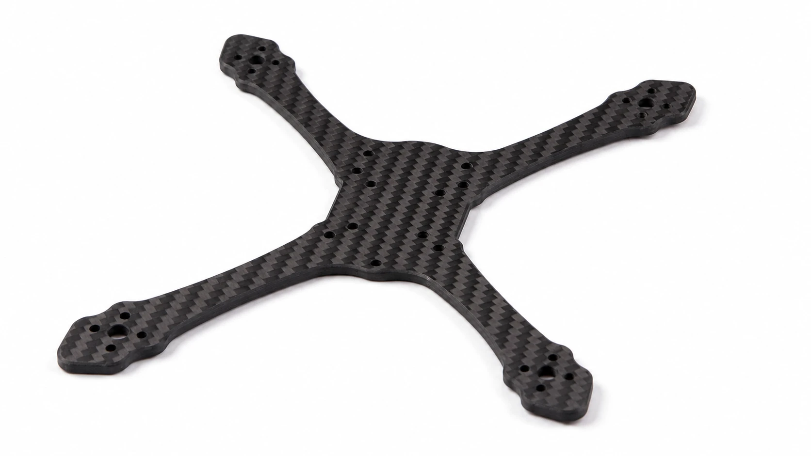
Twenty-one variants did not need twenty-one forming tools
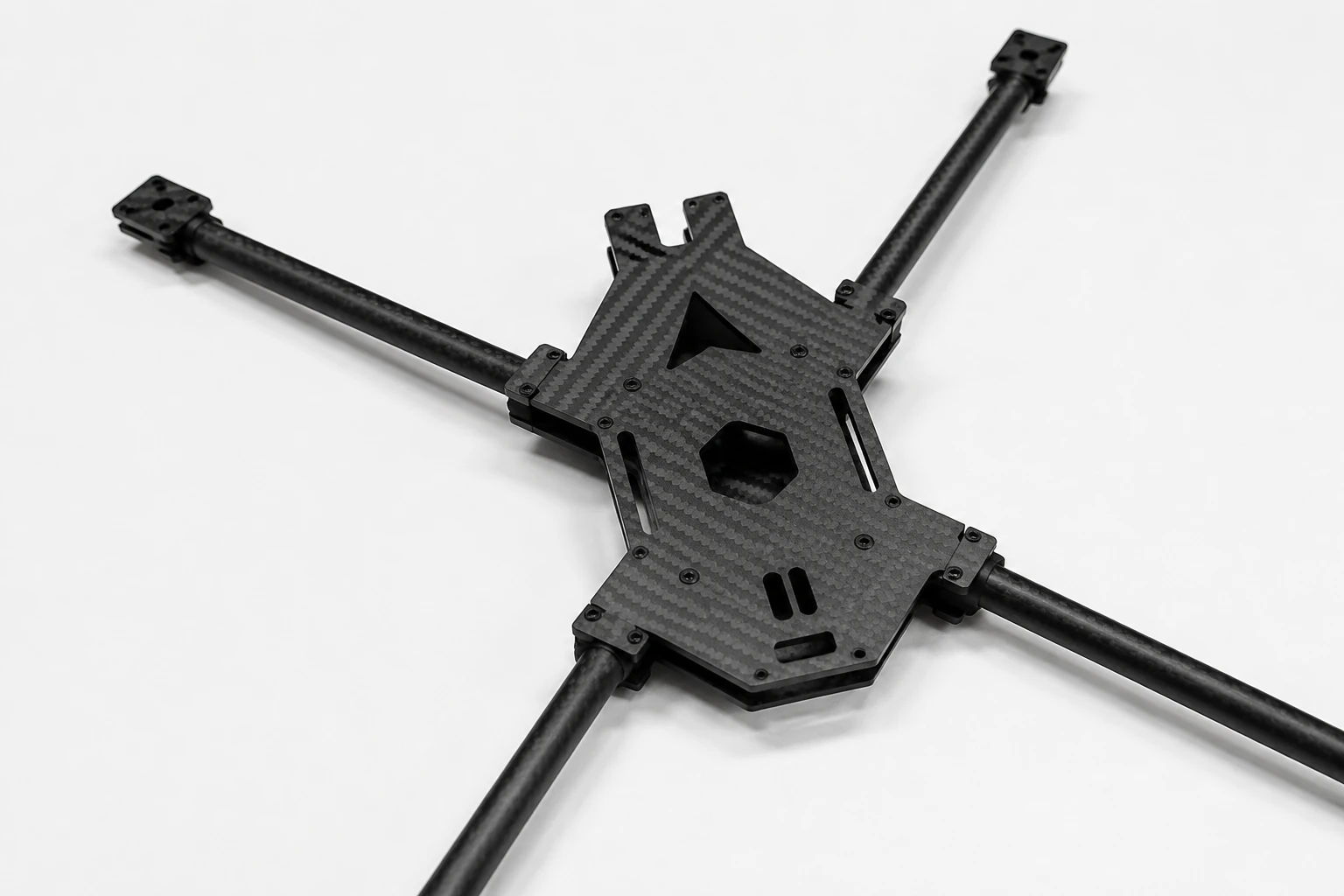
An industrial UAV program contained 21 released frame-plate variants. For a representative 180 × 180 × 2.0 mm, 50-piece configuration, NEXWAVE compared a molding route against autoclave-cured T700 plate plus CNC using the same material, thickness, finish and inspection expectation. The molding concept exposed roughly CNY 500,000 in pre-commitment tooling across the 21 variants. The released plate-plus-CNC route used one controlled program per variant and a dedicated four-part vacuum fixture.
For the representative part, the recorded complete machining cycle changed from 15 to 5 minutes after the dedicated fixture was introduced. The six-month November 2024 to April 2025 record averaged about 550 delivered pieces per month across the 21-variant family. The buyer value was concrete: the product family could be released and repeated without committing to a separate forming tool for every variant.
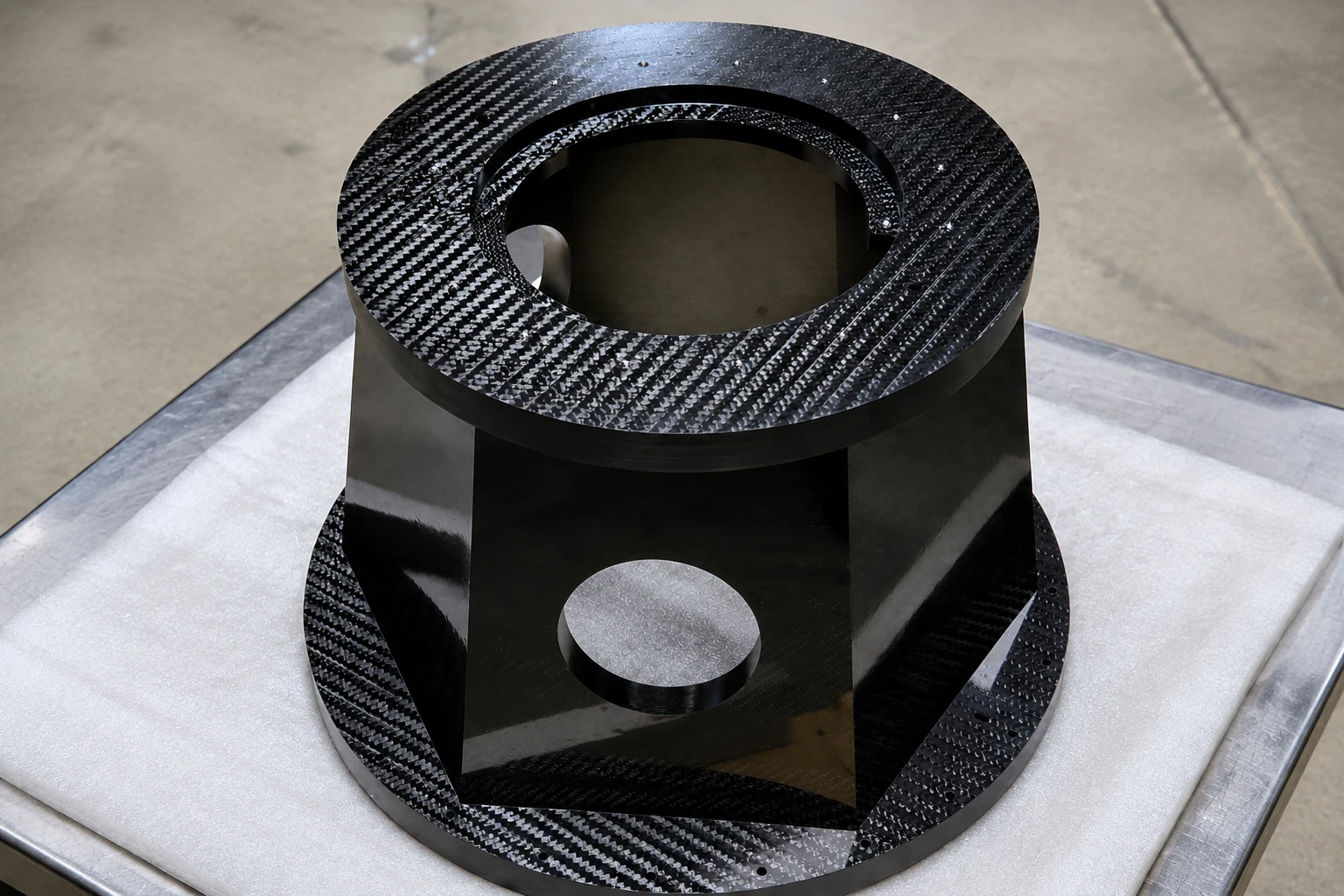
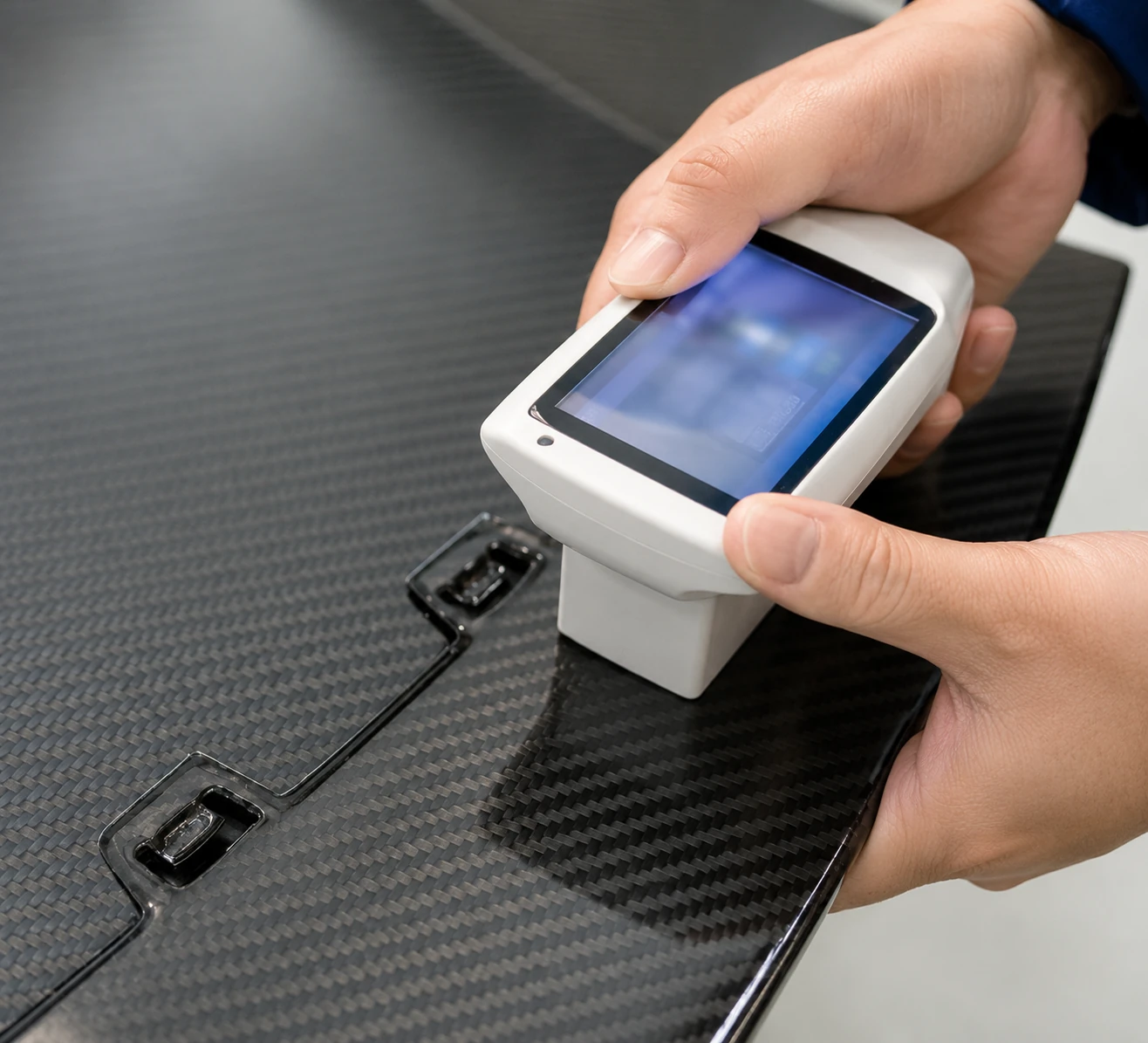
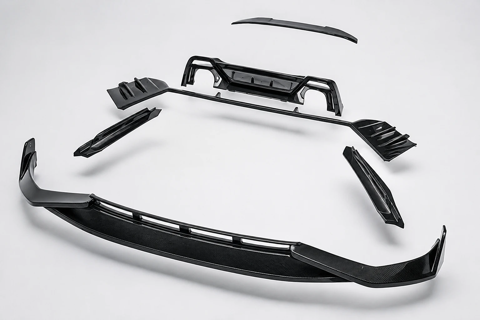
Eight projects, on the record
Build fitment intodatums, tools and machining
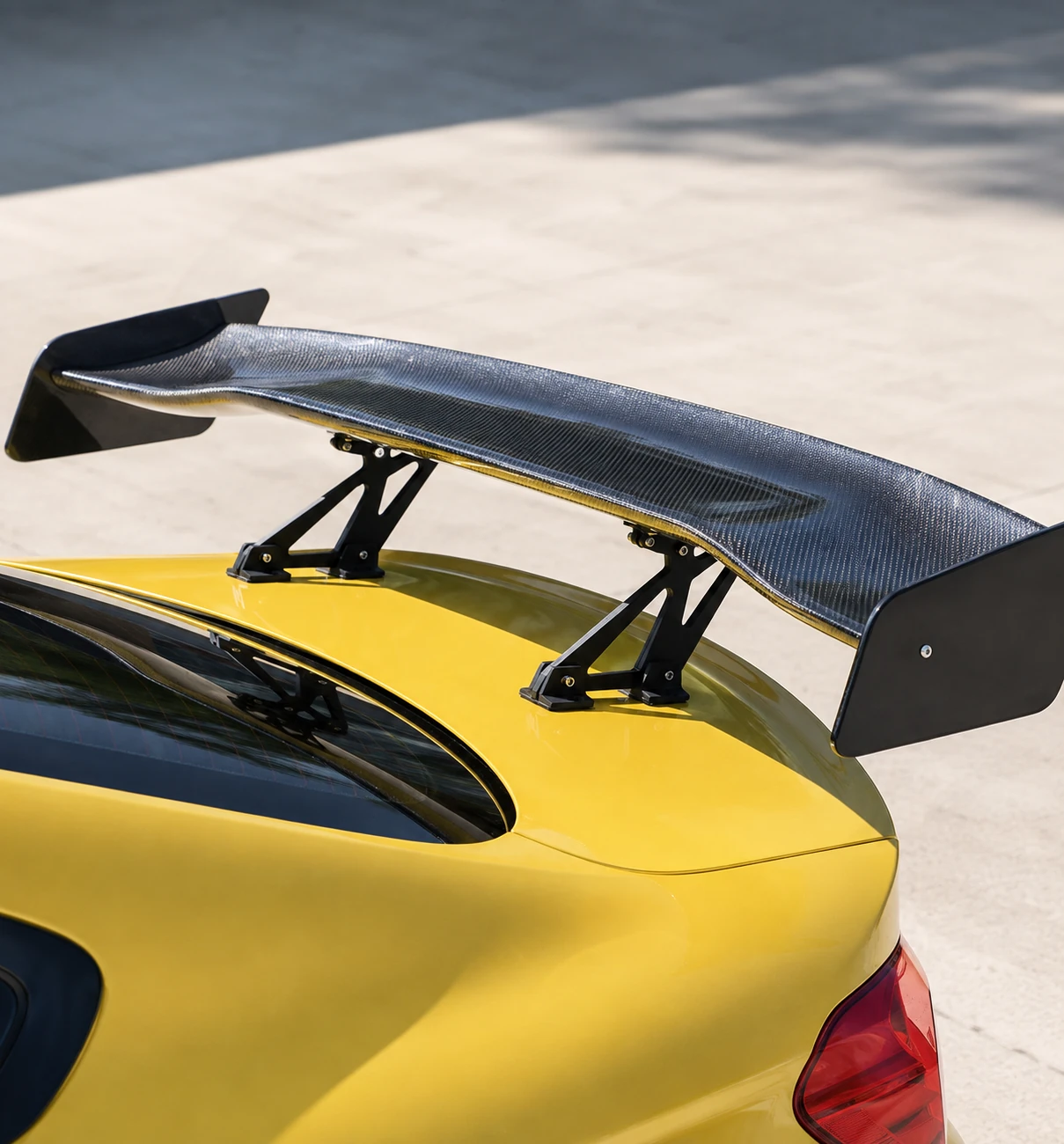
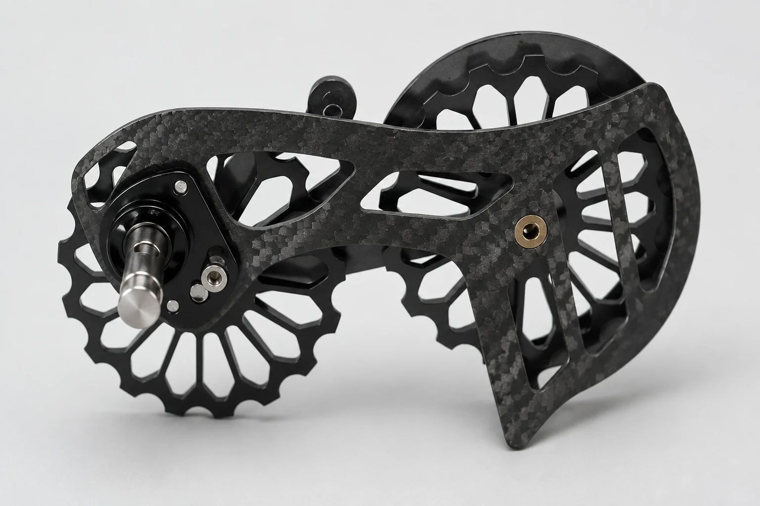
A carbon fiber part can match nominal CAD and still fail at the assembly. The vehicle may have accumulated body variation.
An old source part may have been repaired.
The real mating component may not match the file that arrived with the RFQ. Carbon fiber will not conveniently bend like sheet metal to hide a poor datum decision.
Fitment begins by identifying which source controls the assembly. Depending on the project, that may be the approved 2D drawing and GD&T, released STEP model, source part, mating component, scan, complete vehicle or equipment, gauge or an established production tool. If those sources disagree, NEXWAVE asks the buyer or design authority to resolve the governing condition. Averaging conflicting data would only make the uncertainty harder to find later.
Once the interface is agreed, it is carried through the process:
CAD and CMM can be sufficient when the released interface and mating geometry are reliable. Physical verification becomes important when actual build variation, a flexible assembly, prior modification, a visible gap or flush condition, or a vehicle/equipment installation determines acceptance. Depending on scope, the customer can receive CMM or critical-dimension results, gauge findings, fit photographs, an installed check or an approval record.
A two-millimeter mismatch was not solved by forcing the part
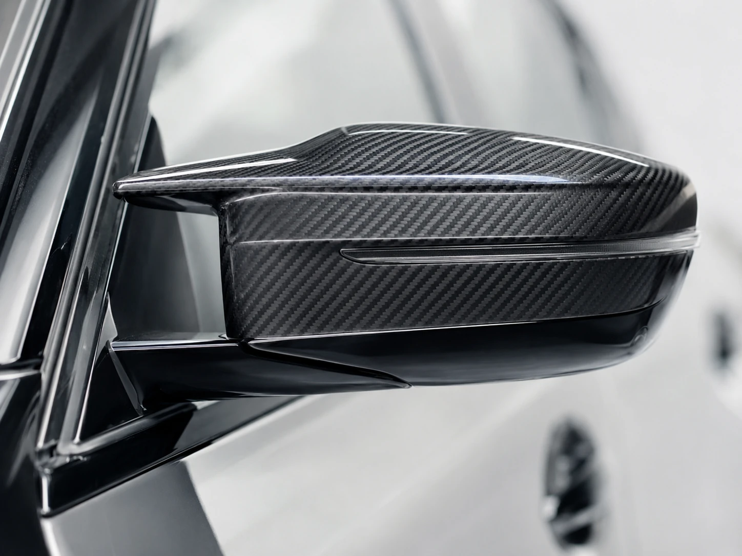
During an anonymous automotive-fender project, a mounting point was about 2 mm out when the part was compared with the actual vehicle. The issue was traced to cumulative body variation against the nominal CAD condition. NEXWAVE used scan data to revise the CNC hole position, then confirmed the installation and visible gap on the vehicle.
The solution was not a promise that every carbon fiber part will “bolt on.” It was a controlled way to decide which assembly condition mattered, transfer it into machining and verify it on the actual installation.
Receive the finished componentyou agreed to buy
A molded shape is not necessarily a finished component. It may still need trim, CNC holes, countersinks, inserts, bonded details, clear coat, paint, hardware, assembly, inspection, labels and packaging. If those responsibilities are unclear, a quotation can look complete while leaving the buyer with another list of suppliers and another round of handling.
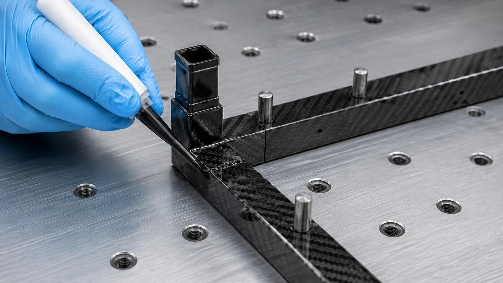
NEXWAVE defines the delivered condition around the physical part. Depending on the project, the supply can connect forming, trimming, CNC work, drilling or countersinking, inserts, bonding, surface finishing, hardware, assembly, inspection, cleaning, protective packaging, labels and selected records. Some work may be completed internally; some may be managed through a qualified project route; and some may remain with the buyer. The quotation must state which is which.
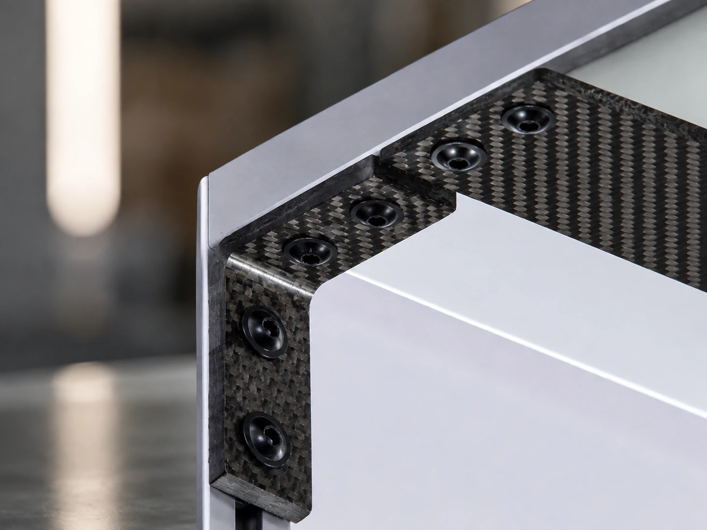
A finished automotive-fender set, not two unfinished shells
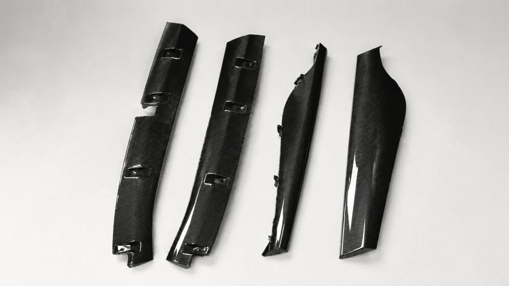
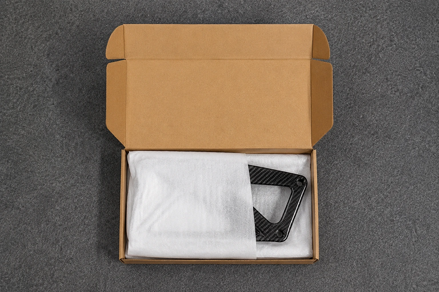
In one representative automotive project, NEXWAVE supplied a left/right carbon fiber fender pair with molding, trim, CNC holes, required inserts and installation hardware, surface finishing, inspection, cleaning, protective packing and project documents. The customer received the finished pair, hardware, an inspection report and installation instructions.
That delivery removed three downstream handoffs from the customer: separate CNC work, finish correction and hardware sourcing. The parts were protected with 5 mm EPE and CNC-cut foam inserts, packed in separate boxes and placed in an export wooden crate. Pack-state photographs, a hardware list and a shipment weight check helped confirm the contents before dispatch.
Catch fit, surface and structural problemsbefore delivery
“Strict quality control” does not tell a buyer what will actually stop a bad custom part from shipping. The useful question is simpler: what can make this particular part unusable or unacceptable, and where will that condition be checked? The answer changes with the part.
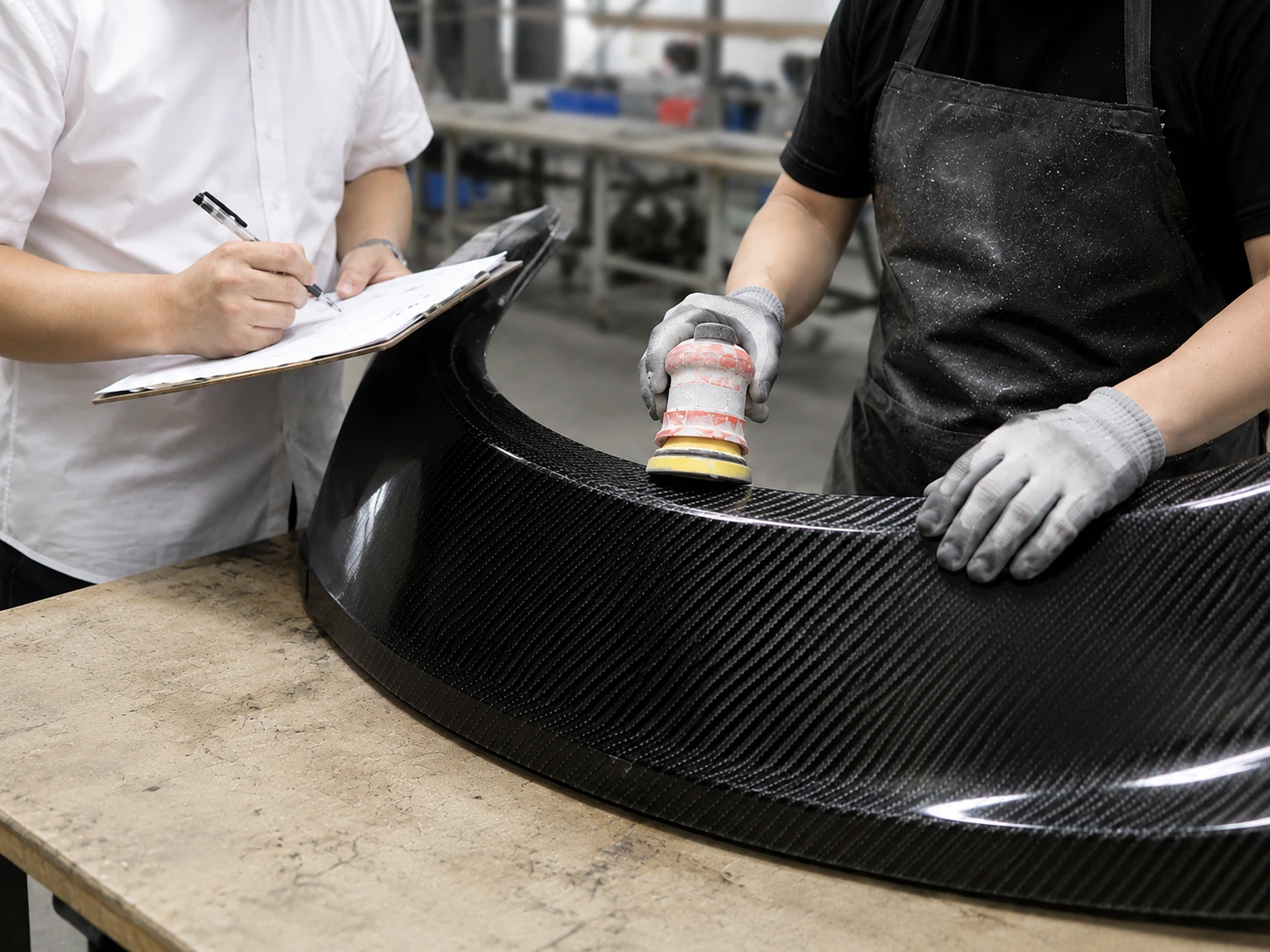
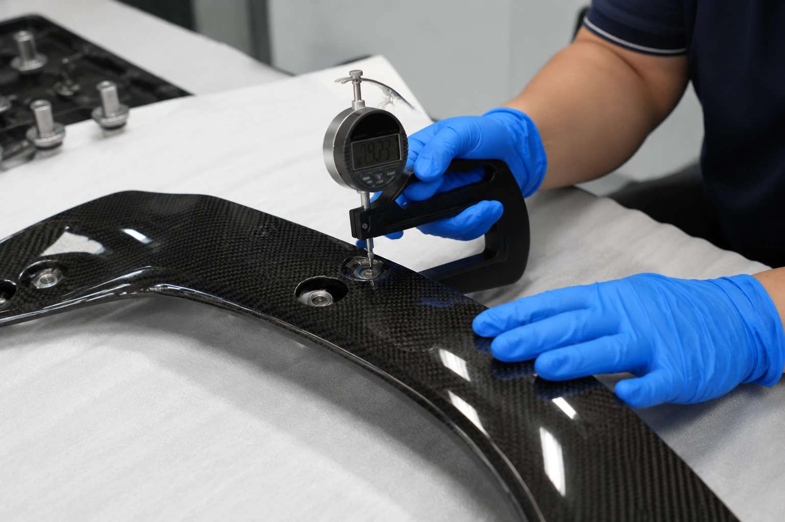
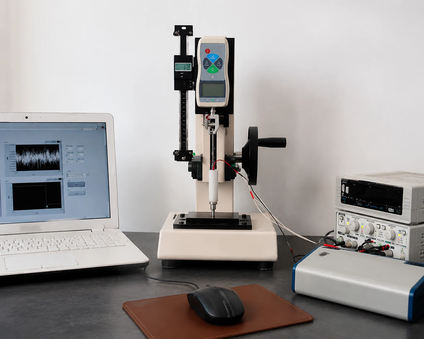
Three suspect parts were stopped before shipment
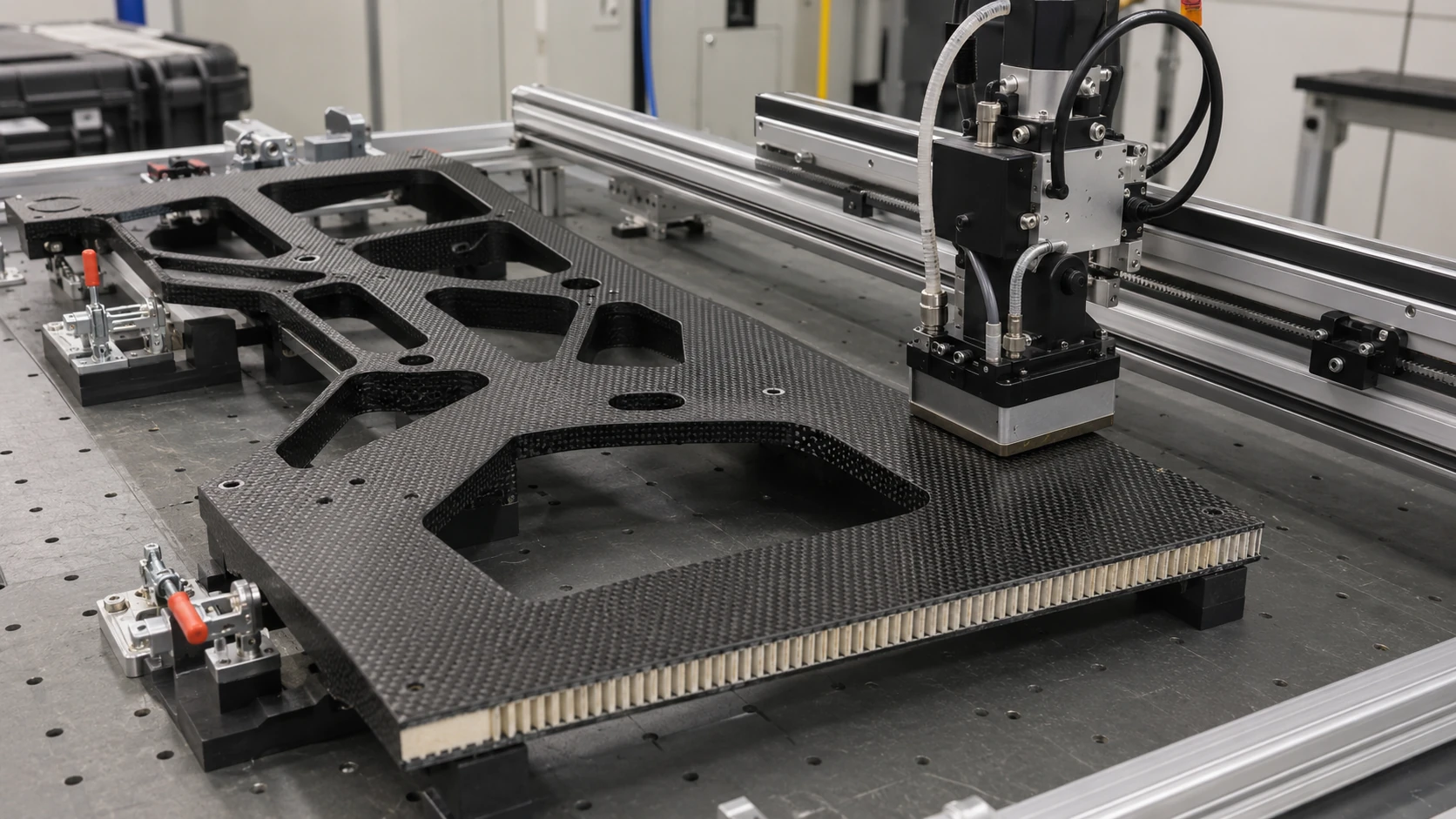
On an anonymous UAV sandwich frame-plate project, the project C-scan acceptance level was below 2 percent. Three parts in a 12-piece group showed a local 3.5-percent indication. NEXWAVE traced the problem to a vacuum-bag leak, changed the bag material and vacuum monitoring, remade the three parts and confirmed that the replacements passed the project C-scan requirement.
The customer did not have to discover those parts during assembly or operation. What the case proves is the control logic: the check was tied to the actual sandwich structure, the affected scope was identified, the process cause was corrected and replacement parts were verified before release.
Make the next ordermatch the accepted part
An approved sample is useful only if the factory can explain how it was made. If it passed after someone hand-trimmed an edge, added a shim, held it differently in a fixture or touched up a surface, that hidden correction will not automatically appear in the next batch.
NEXWAVE turns the accepted result into a production reference. Depending on the project, that reference can include:
Any manual correction that made the sample pass must be resolved before repeat release. The change may belong in CAD, the tool, a fixture, the CNC program, a work instruction or the inspection definition. The goal is not more paperwork. It is to make sure the next operator and next order can reproduce the accepted condition without relying on memory.
A hand-trimmed edge became a controlled CNC correction
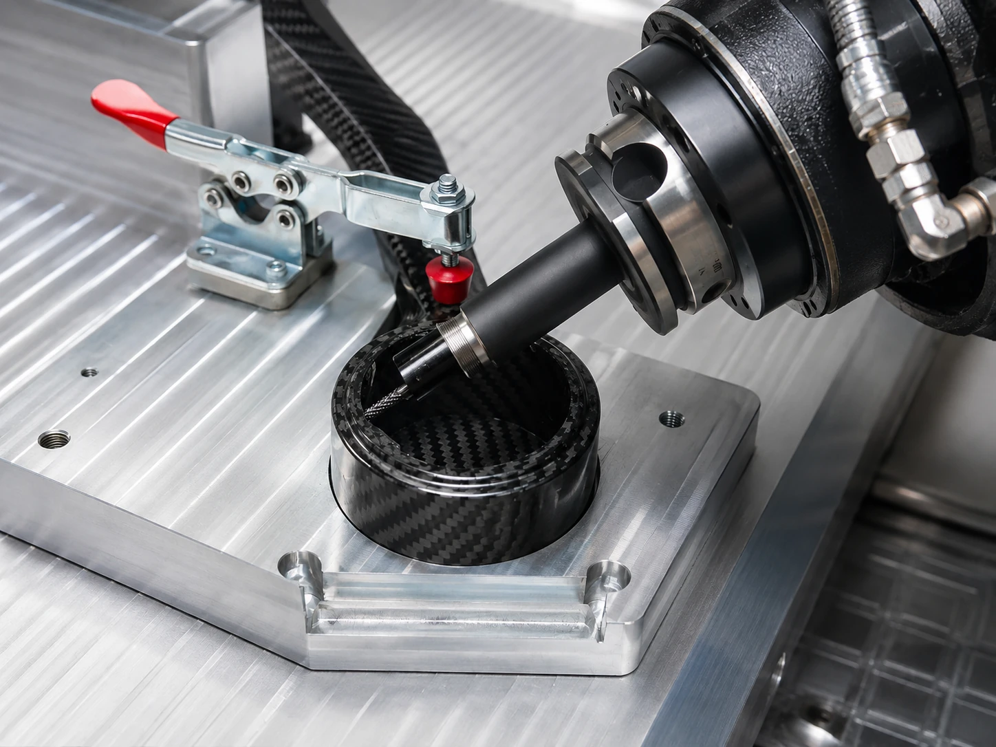
During the BMW E46 carbon fiber foot-tray program, an approximately 0.5 mm edge burr was traced to CNC tool compensation. NEXWAVE corrected the program, remade the part and obtained acceptance. Later batches no longer depended on hand edge trimming.
That small example captures the purpose of a repeat-production baseline. The accepted result was not stored as “make it like last time.” The actual correction moved into the process that produced the next part. This reduces repeated approval work, hidden hand finishing and the risk that a later order drifts away from the sample the customer accepted.
Keep delivery, acceptance and changestied to the same part definition
The engineering and manufacturing solution still needs three concise controls:
What physical work, hardware, finish, assembly, packaging and documents NEXWAVE supplies, and what remains with the buyer.
The governing revision, critical characteristics, inspection method and frequency, required records, approval authority and conditions for moving forward.
How a planned design or process change is approved, and what evidence preserves the identity and condition of a part when an unexpected problem is found.
Asked before the first file is sent
Yes, for a preliminary review. Photographs with reference dimensions, an existing component or a physical sample can reveal part form, interfaces and likely problem areas. Final geometry, fitment, tolerances and the manufacturing basis still need to be confirmed before tooling or production is approved.
NEXWAVE can review custom components against customer-controlled drawings and confirmed requirements. Project suitability, component testing, documents and approval responsibilities are reviewed separately. Manufacturing support does not equal product certification, type approval or regulatory release.
No. They depend on geometry, material and process route, tooling, quantity, finish, inspection, validation, included delivery work and the information still open. The project quotation should state the applicable figures and the conditions behind them.
Bring the part problem,not a perfect RFQ
Send the CAD, drawing, sample, existing part, photographs or failure information you already trust. NEXWAVE will identify what can move forward, what still needs confirmation and which engineering or manufacturing action should address the real part problem first.