
CARBON FIBER MANUFACTURING AND SUPPLY
CarbonFiberManufacturerFromDesigntoDelivery
NEXWAVE helps OEMs, engineers, procurement teams, distributors and brands move from an existing requirement—or an unfinished idea—to a clear manufacturing and supply route.
Factory in Tengzhou, Shandong · 80+ employees · 30+ composite design engineers
NXW / INDUSTRIAL SYSTEM · REV. 01
SCROLL02 · ROUTE SELECTION
Choose the Right Path for YourCarbon Fiber Project
You do not need to select a manufacturing process before contacting us. Start with the result you need and the information you already have. We will help you identify the right commercial and technical path.
01 / SELECT PATH
Carbon Fiber Products
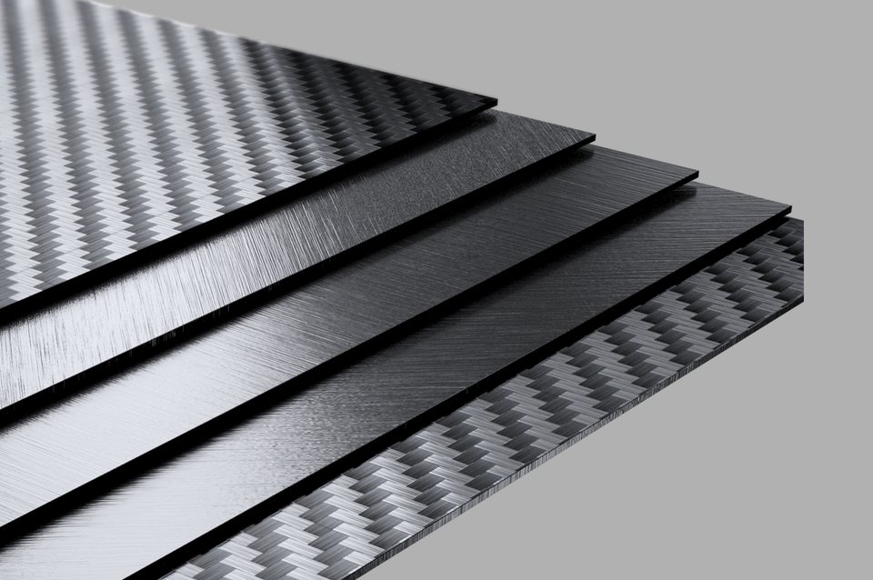
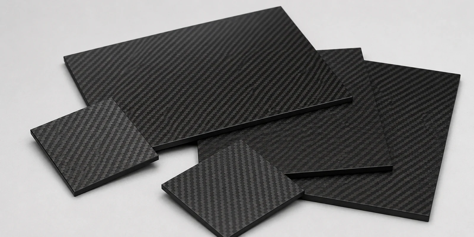
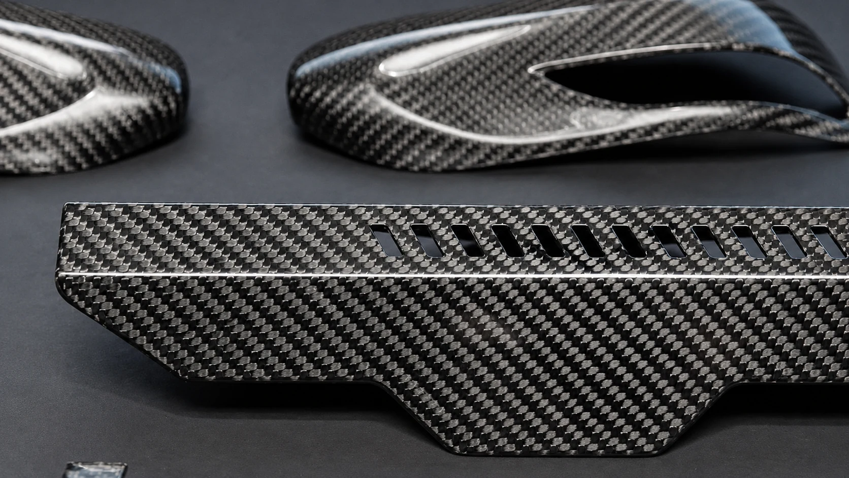
Start here for an existing product form or a known component family. NEXWAVE supplies panels and plates, tubes and rods, and molded product forms.
Share the product type, required dimensions or specification, surface expectations and quantity. We will confirm the available form and the information needed for quotation. Sizes, configurations, MOQ and timing vary by product and quantity.
02 / SELECT PATH
Carbon Fiber Materials
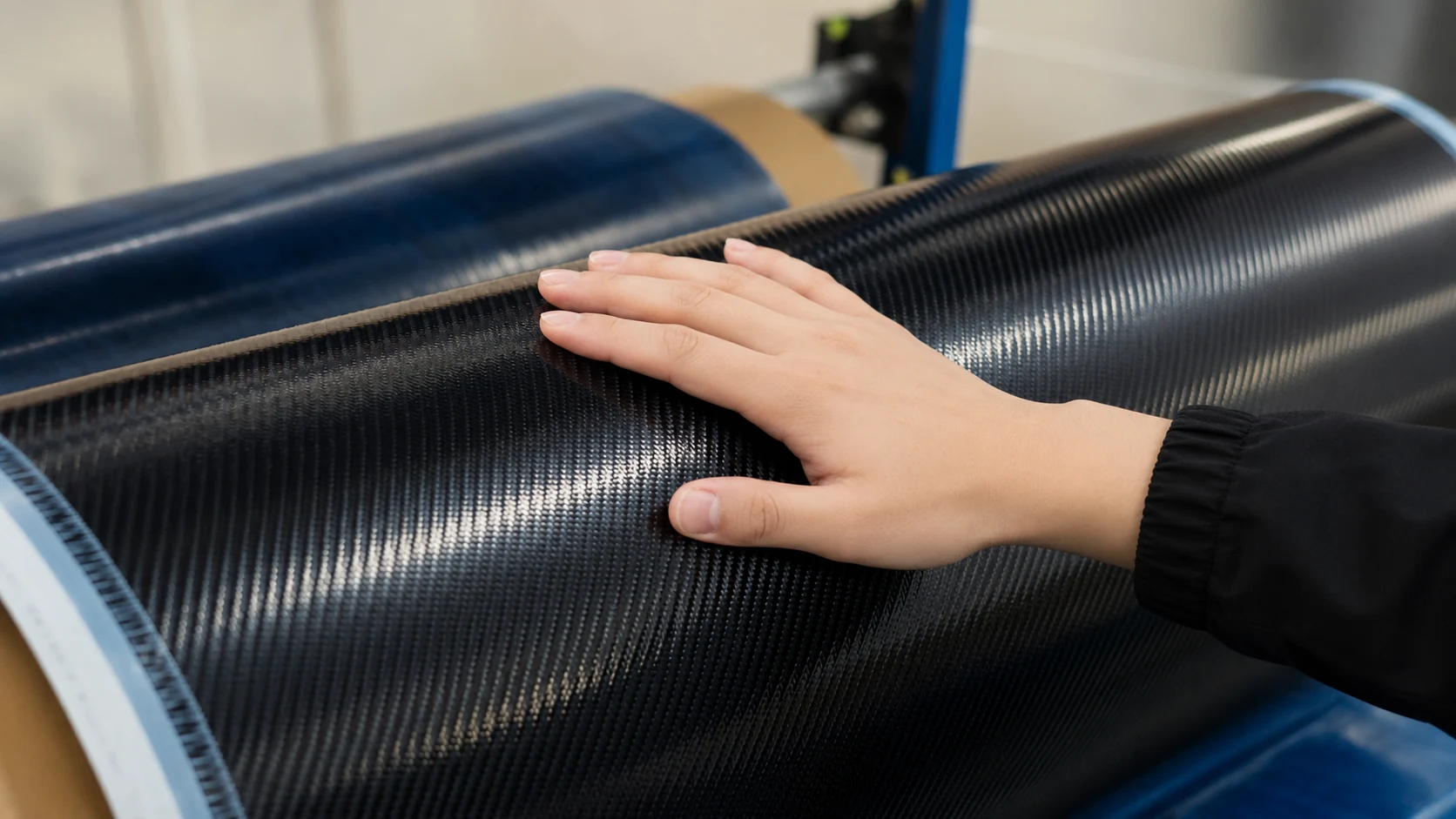
Use this path for tow, woven fabric, dry unidirectional material, UD tape, prepreg or another available material form. Send the form, grade or performance requirement, dimensions, quantity and intended process.
We consider fiber data together with the resin system, laminate, manufacturing process and validation conditions. This gives your team a more useful basis for selecting the material than a grade name alone.
03 / SELECT PATH
Custom Carbon Fiber Parts
This path fits a part that is unique to your drawing, sample, assembly or performance target. You can start with a complete CAD model, a 2D drawing, an existing metal part, a physical sample, photographs or an unfinished concept.
We review what you have and identify the next practical step: DFM, process selection, tooling, samples or quotation.
04 / SELECT PATH
OEM, ODM and Private-Label Programs
Choose this path for an ongoing product program, contract manufacturing, a private-label product or a development partnership. Helpful inputs include the product objective, responsibility split, forecast or quantity range, approval expectations and supply plan.
Together, we define development responsibilities, included manufacturing work, approval stages, change control and repeat supply. Detailed responsibilities and commercial terms are confirmed during the program review.
If none of these paths feels exact, send what you have. We will help you identify where the project fits and what to define next.
Planned page links activate only after each destination is published and passes link-readiness checks.03 · NEXWAVE — CARBON FIBER AUTOMOTIVE
Automotive Part MoldsReady.
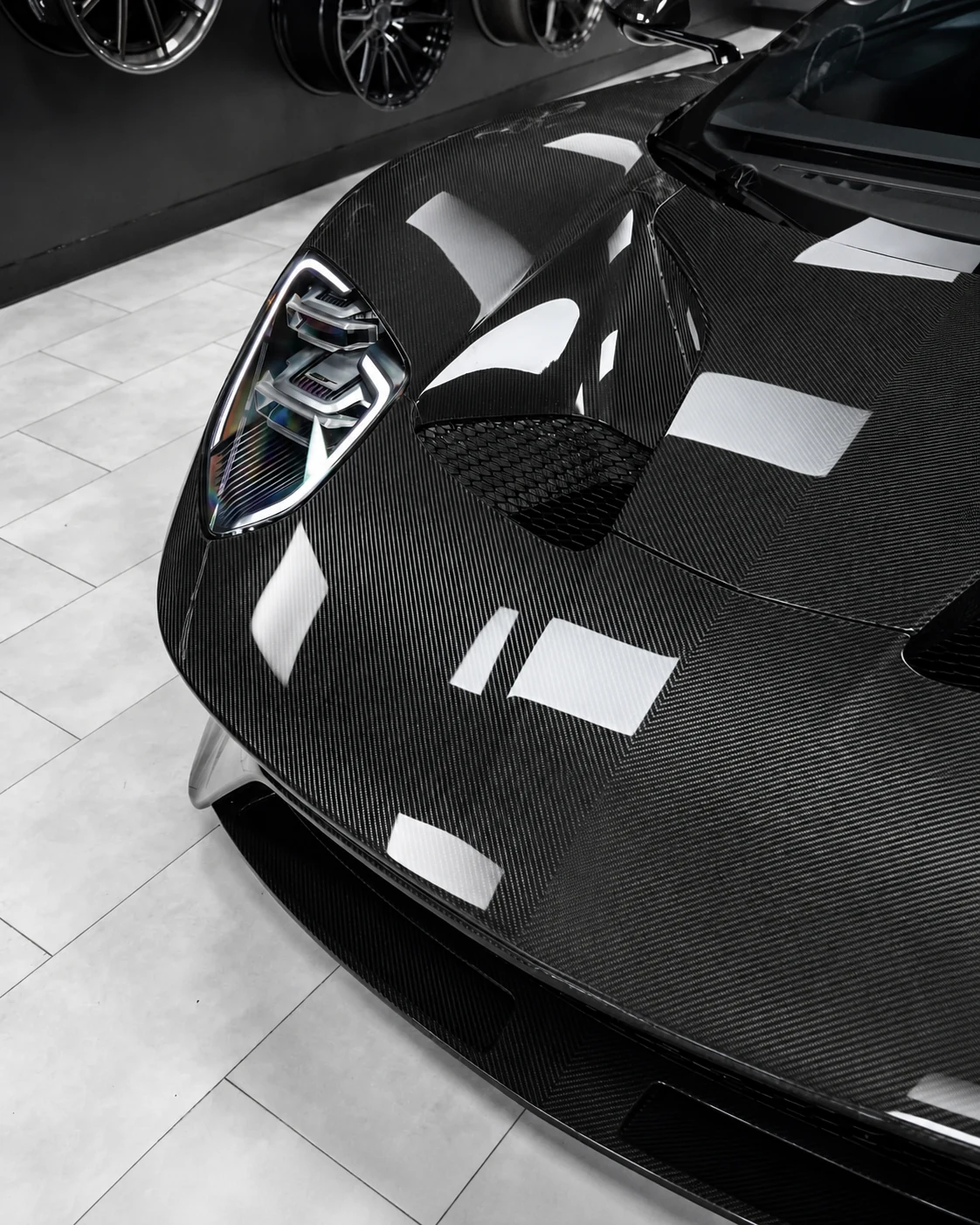
NEXWAVE maintains more than 500 molds for carbon-fiber automotive parts across multiple vehicle platforms. When an existing mold matches the required vehicle specification and part version, you can skip a full new-tooling cycle, reduce or eliminate the cost of new tooling, and move sooner into sample production.
Mold availability and fitment are confirmed based on the vehicle model, year, chassis code, body style, trim and exact part version. Left- or right-hand-drive configuration, sensor and camera positions, exhaust layout and other vehicle-specific differences are checked when they affect the part.
Existing-Mold
Fast Track
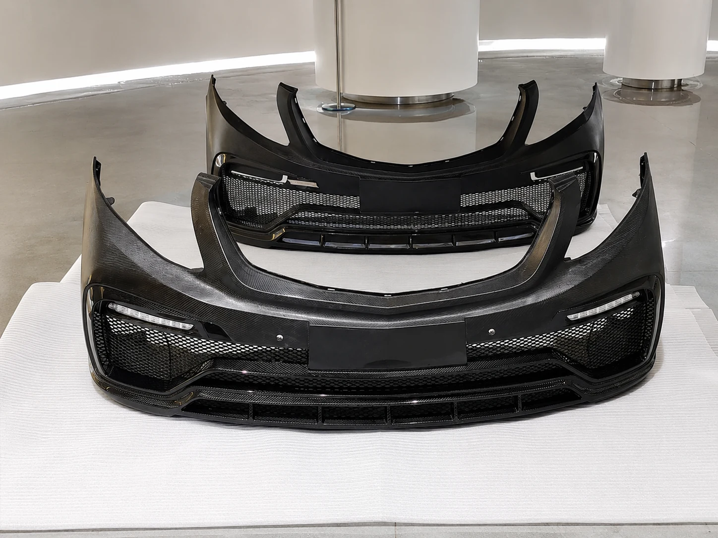
We begin with a complimentary preliminary fitment and DFM review based on the vehicle, part, mounting points, visible surfaces and available project information.
If detailed reverse engineering, scanning, CAD reconstruction or further engineering development is required, that work is defined separately.
- Confirm the vehicle, part and available mold.
- Agree on mounting, finish and first-order requirements.
- Produce the first sample.
- Review fit, mounting points, surface quality and finish.
- Approve the part for production.
New Automotive
Part Development
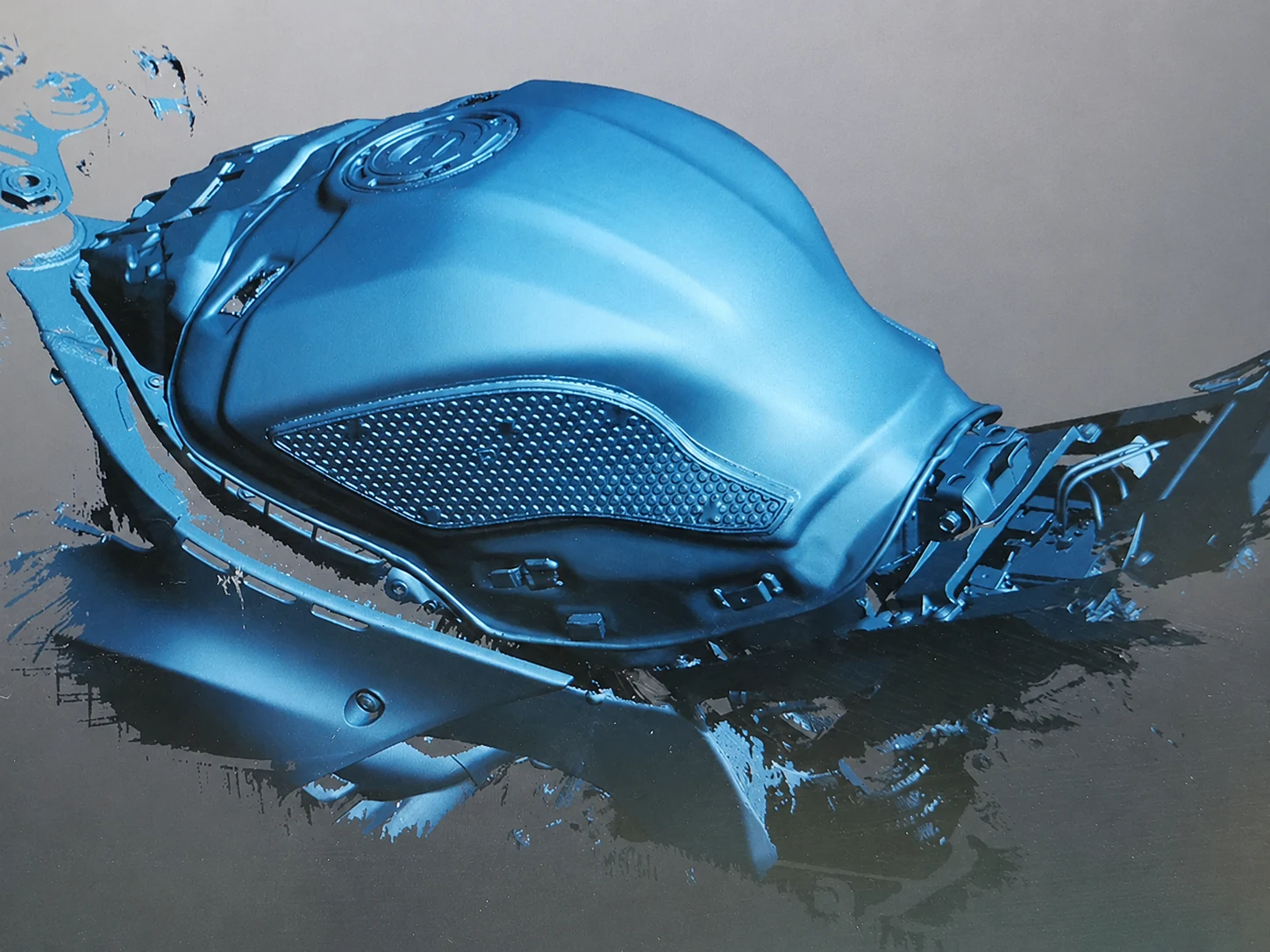
If no suitable mold exists—or the structure, appearance or interfaces need to change—we can start from CAD, scan data, a sample, photographs or vehicle information. Fitment and DFM review lead into tooling, sample production and approval before the part enters production.
PHASE 03 · REPEAT ORDERS
Carry the Approved Version Into Repeat Orders
Before production, we confirm whether the part uses exposed or painted carbon fiber, the weave direction, gloss level, edge treatment, mounting details and visible-surface standard. Once the sample is approved, the part version, finish, inspection requirements and packing method become the reference for future orders.
Approved molds can be stored, maintained and prepared for later production according to the program agreement. This helps your team reorder without rebuilding the project definition, while packaging and international-delivery needs can be planned before production approval.
Send the vehicle make, model, year, chassis code, body style, trim, required part and destination so we can check existing-mold availability or define a new-development route.
Request a Project Review →04 · NEXWAVE — COMPOSITE ENGINEERING
Start with a Drawing, Sample,Existing Part, or Unfinished Concept.
You can begin before every composite detail is fixed. The first engineering review turns your current information into a clearer next step; you do not need to arrive with the material, layup, tooling and process already solved.
01 / INPUT
Send the Best Information You Have
Useful starting points include:
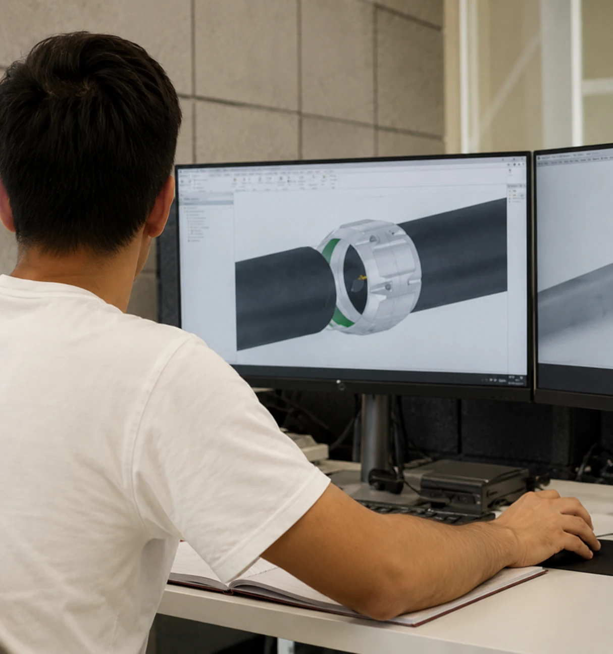
- a neutral 3D file format such as STEP, IGES or Parasolid;
- a native CAD file with the software version identified;
- a 2D drawing, DXF, DWG or dimensioned PDF;
- a physical sample or an existing metal or composite part;
- photographs with known dimensions and a clear explanation of use; or
- a performance target, assembly requirement or early product concept.
02 / ORGANIZE
We Organize the Engineering Questions
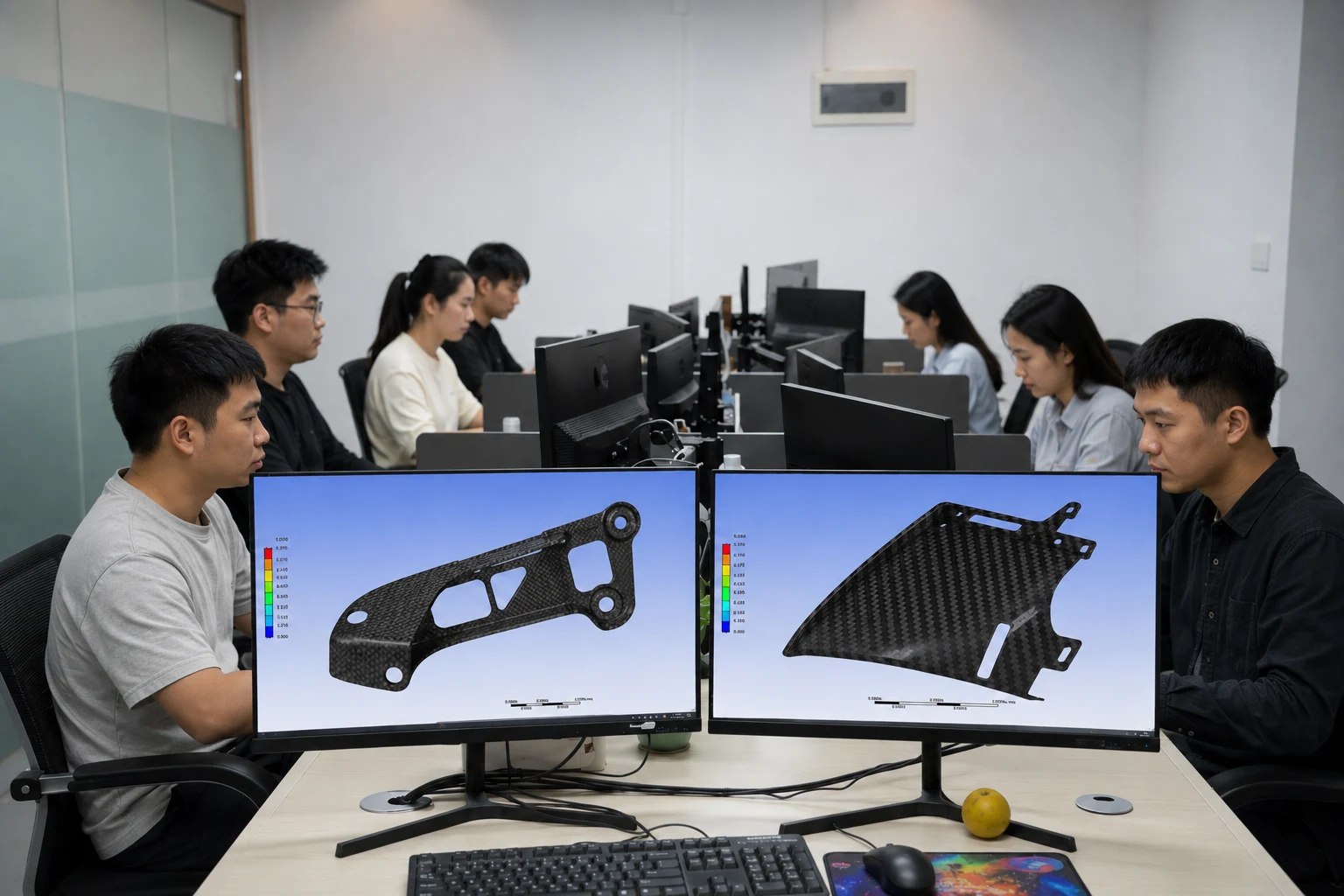
We first define what the part must do and how it connects to the surrounding assembly. The review then groups the technical questions into five practical areas:
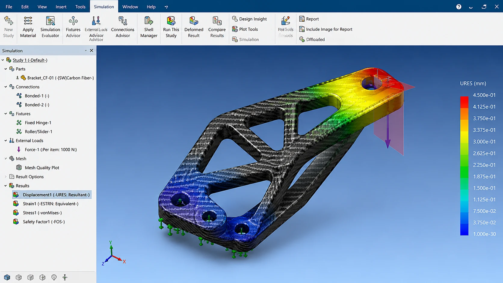
A metal part converted to carbon fiber may need different wall transitions, local reinforcement or insert geometry rather than a direct material substitution. Tool access, release, bonded interfaces, galvanic isolation and inspection access can also change the design.
03 / OUTCOME
The First Review Gives Your Team a Clearer Next Step
You receive a practical view of what is missing, which assumptions or risks matter, the likely manufacturing approach, initial tooling or sample considerations, preliminary inspection needs and the next decision.
- what is missing
- which assumptions or risks matter
- the likely manufacturing approach
- initial tooling or sample considerations
- preliminary inspection needs
- the next decision
More than 30 NEXWAVE composite design engineers support questions involving load paths, laminate design, interfaces, reinforcement, process selection and manufacturability. They help your team define a viable target, with final performance established through the agreed material, structure, process and validation plan.
ENGINEERING SUPPORTFewer Handoff Gaps. Clearer Ownership. Better Alignment.
Engineering, production and quality decisions stay connected, helping reduce repeated explanation, avoidable rework and late changes. This gives your team a clearer path from the first review into production.
05 · MANUFACTURING CAPABILITY
The Right Manufacturing CapabilityStarts With the Part
We match the manufacturing approach to the part rather than asking the part to fit a standard process. Geometry, material structure, tooling, quantity, surface and approval requirements guide the choice.
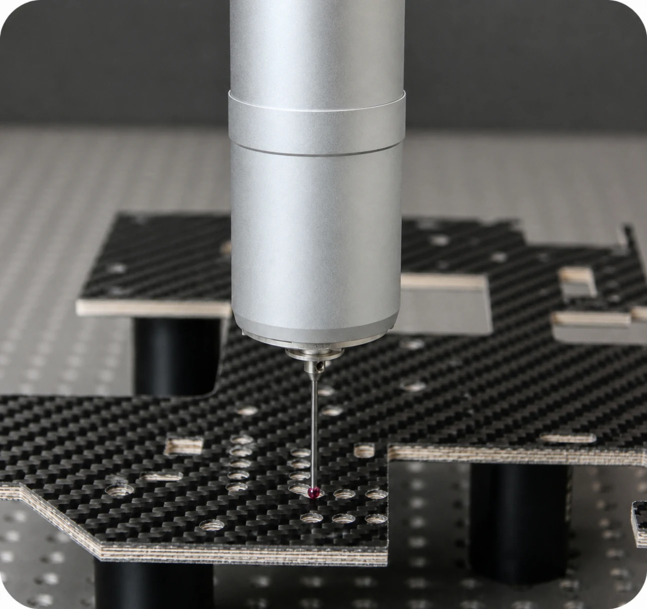
01 / CONTROLLED OPERATION
Match the Forming Method to the Part
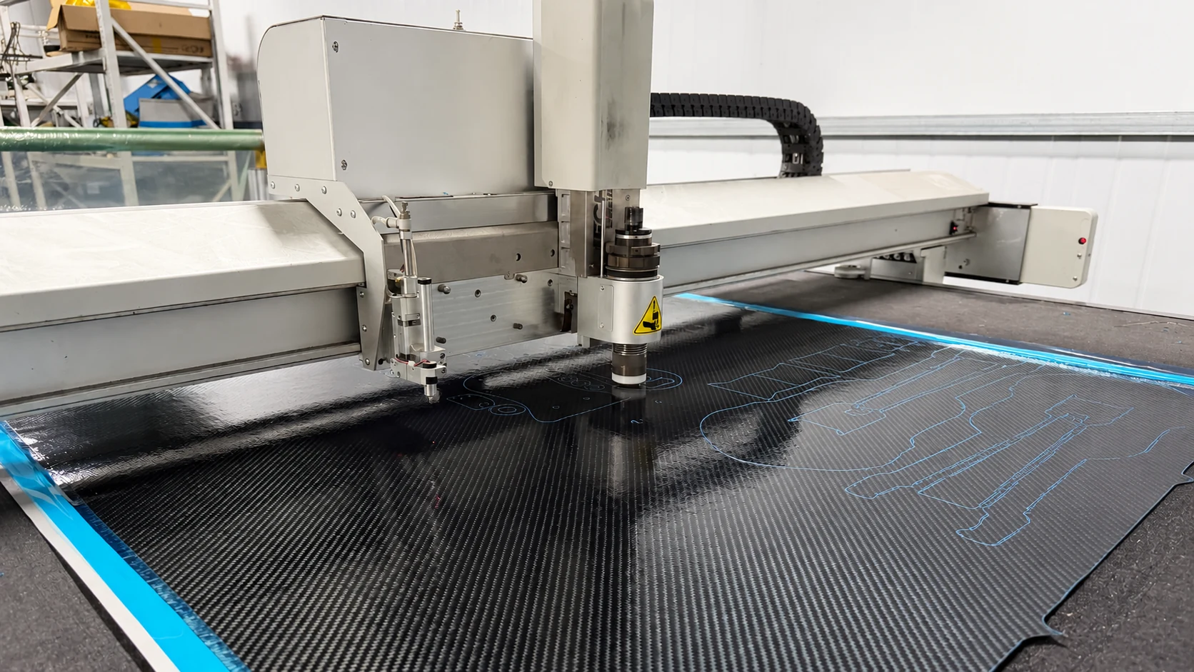
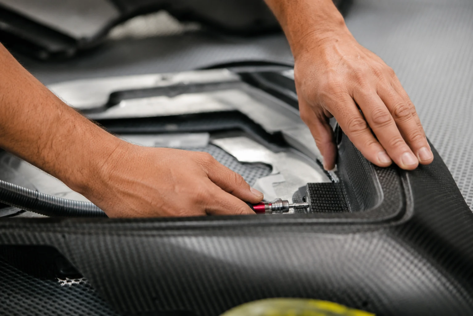
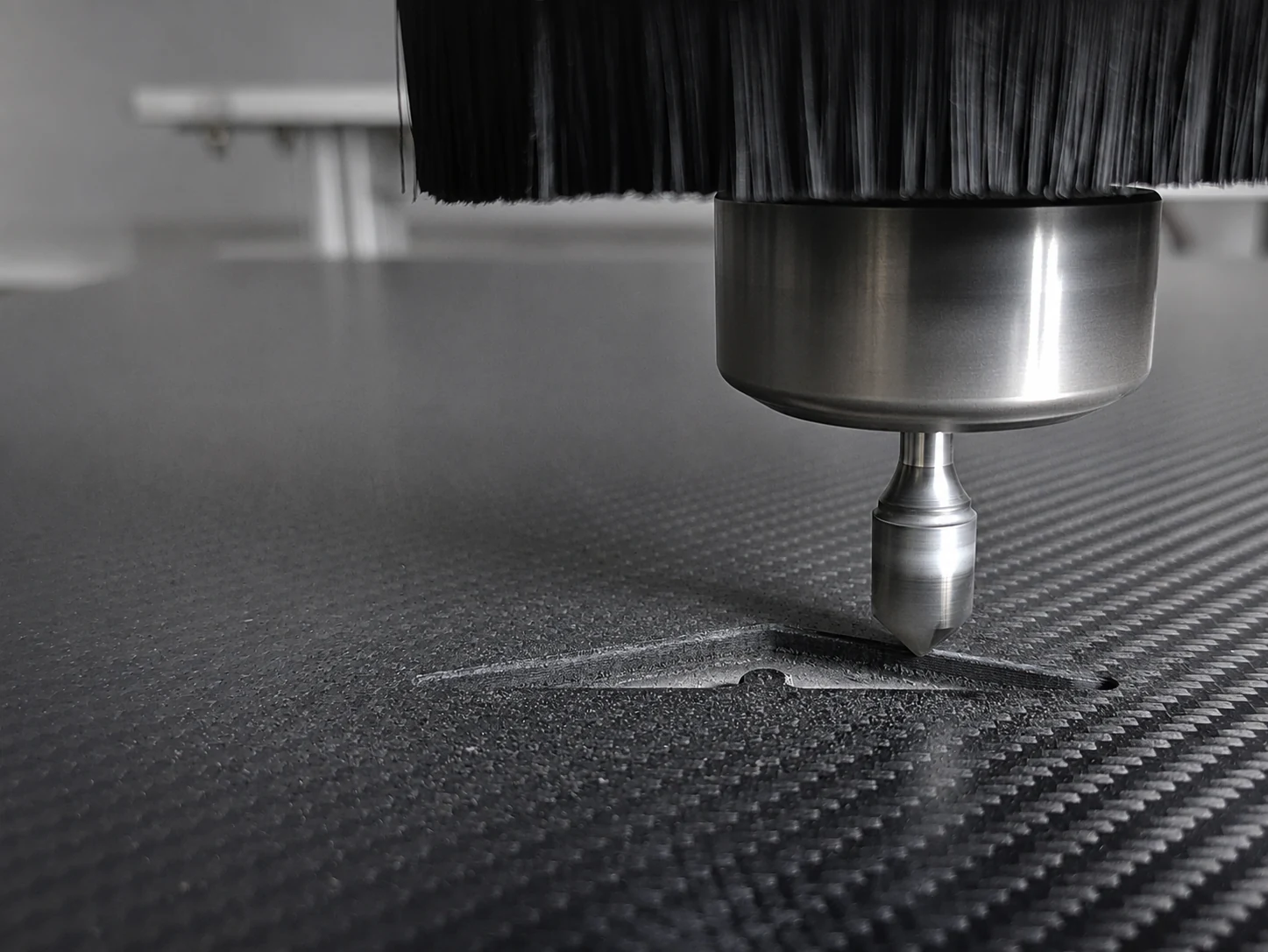
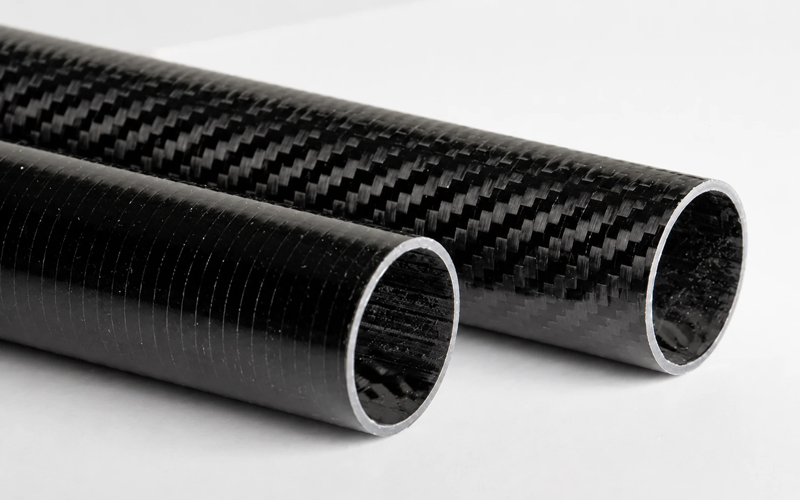
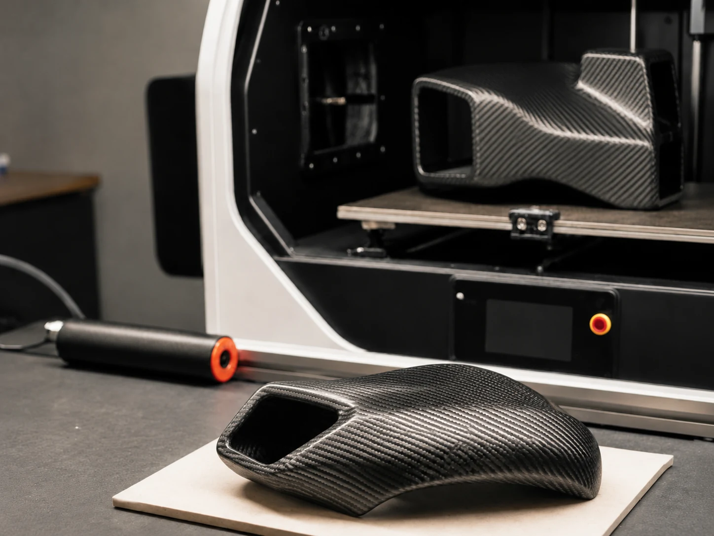
NEXWAVE’s in-house capabilities include prepreg production and cold storage, automated cutting, controlled layup, vacuum bagging, autoclave curing, hot pressing, compression molding, forged carbon molding, filament winding and tube rolling.
We narrow the method by part envelope, laminate design, tool configuration, thermal cycle, surface expectation and production quantity. This gives tooling and sample planning a specific technical starting point.
STAGE 01 · Engineering
Confirm the Engineering Definition
We organize the best available part information into an agreed definition and a visible list of open questions. Both teams leave this stage with the same understanding of the part and the next decision.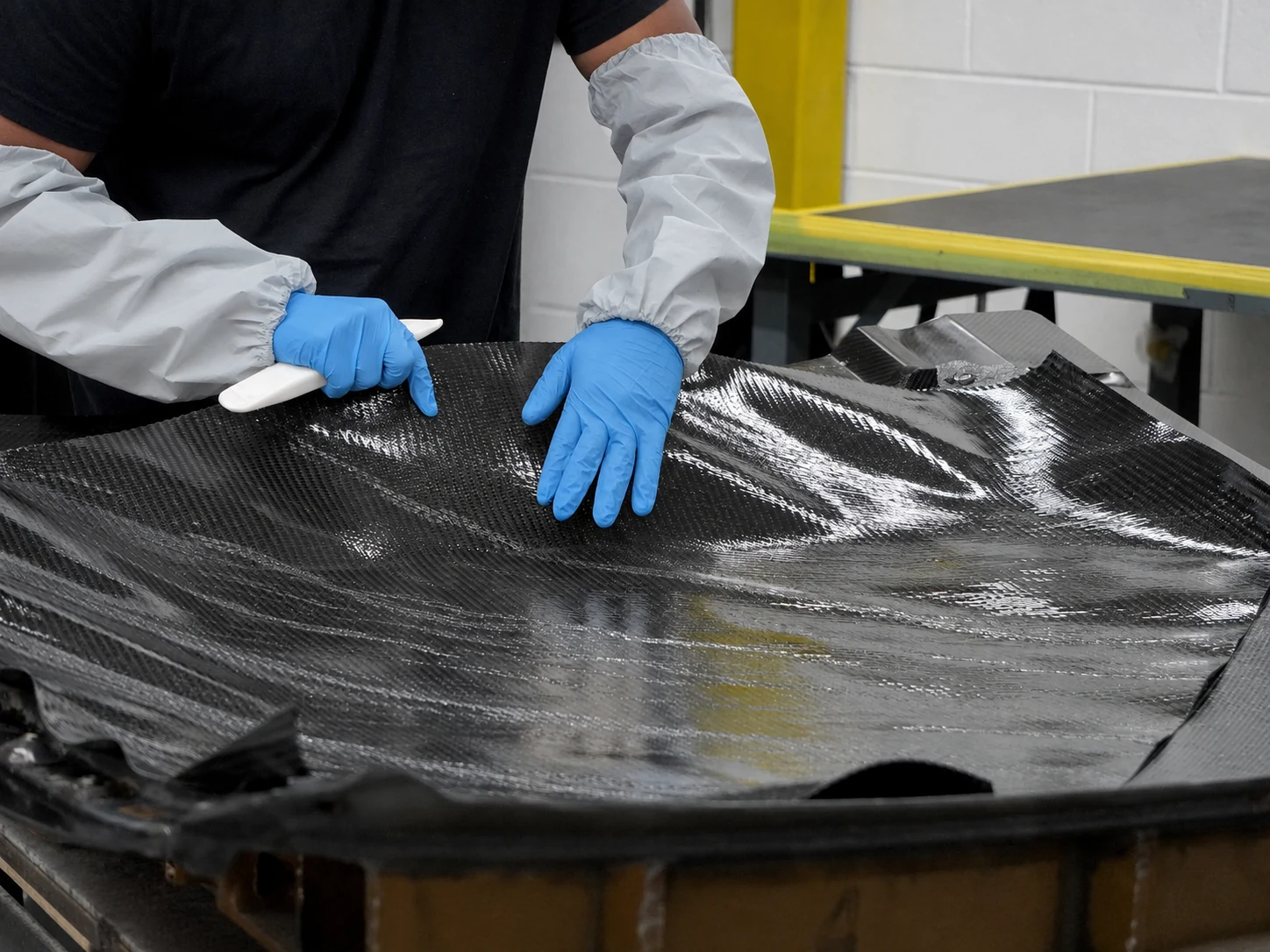
STAGE 02 · Materials + Tooling
Agree on the Manufacturing Approach
Together, we agree on the material and manufacturing approach, tooling direction and validation plan. Customer-specified materials, suppliers, tests or approval steps are identified before tooling, samples or formal quotation.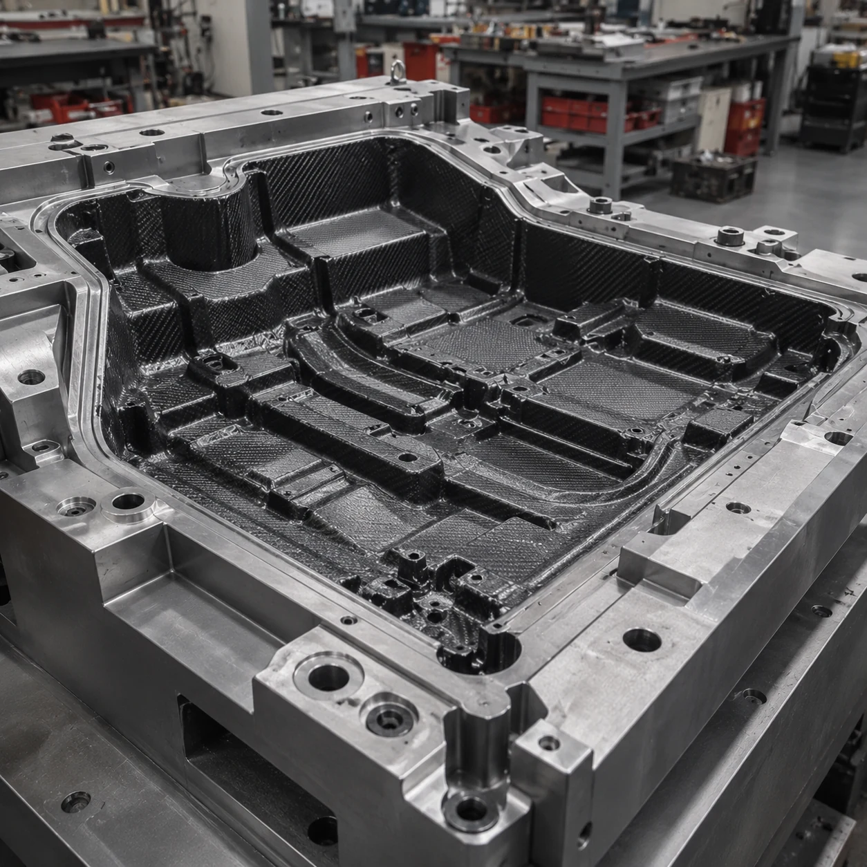
STAGE 03 · Tooling + Samples
Build the Tooling and First Parts for a Clear Purpose
A concept prototype, appearance sample, structural validation part and production-intent part may need different tools and approval evidence. We align the tool, sample method and initial checks with what the first part must prove.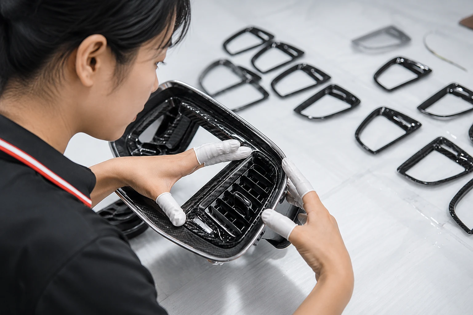
STAGE 04 · Validation
Use Validation and Pilot Production to Close Open Questions
Engineering samples, appearance samples and pilot batches answer different questions. We confirm which dimensions, fit, surface, structure, assembly or process result each stage needs to demonstrate before production. This creates an approved reference and a clear list of changes to close before production.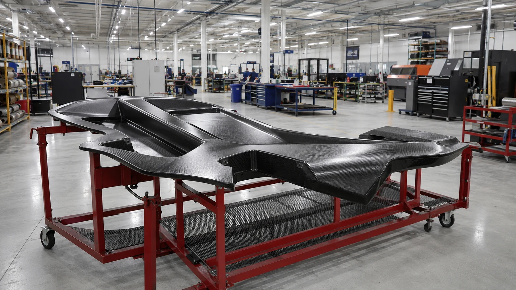
STAGE 05 · Production
Produce and Approve Against the Agreed Requirements
Production follows the approved part, material, tooling and process definition. Parts move forward after the agreed inspection and approval requirements have been met.
STAGE 06 · Delivery + Repeat
Prepare Delivery and Make Repeat Orders Easier
The approved part moves into order-specific packing, documentation and delivery preparation. Repeat orders follow the approved part, process and inspection requirements, so the project does not need to be redefined each time. Tooling storage and maintenance follow the program agreement.07 · ACCEPTANCE DEFINITION
Agree on What Makes the PartAcceptable Before Production
QCP / REV. 04 · PROJECT-SPECIFIC QUALITY FRAMEWORK
Before production begins, both teams agree on what makes the delivered part acceptable. NEXWAVE then connects those requirements to the relevant process checks, inspection methods and reports.
When a sample-first plan is used, the agreed critical features, interfaces, appearance and functional requirements are checked before the part is approved for repeat production.
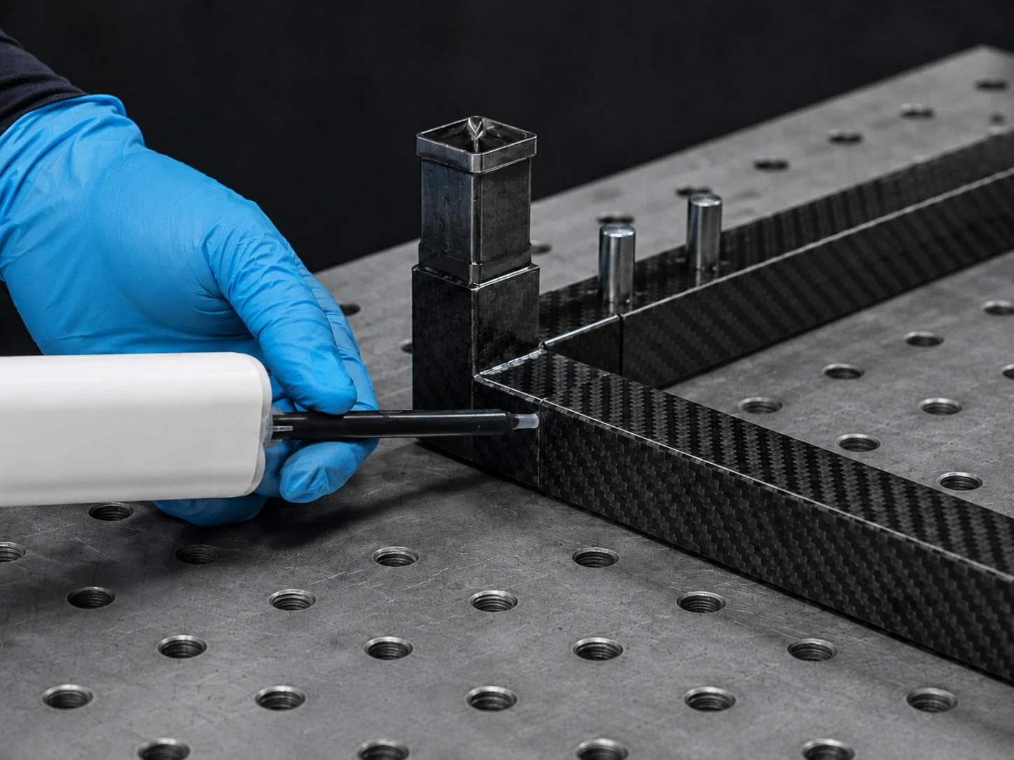
Turn Expectations into Clear Checks
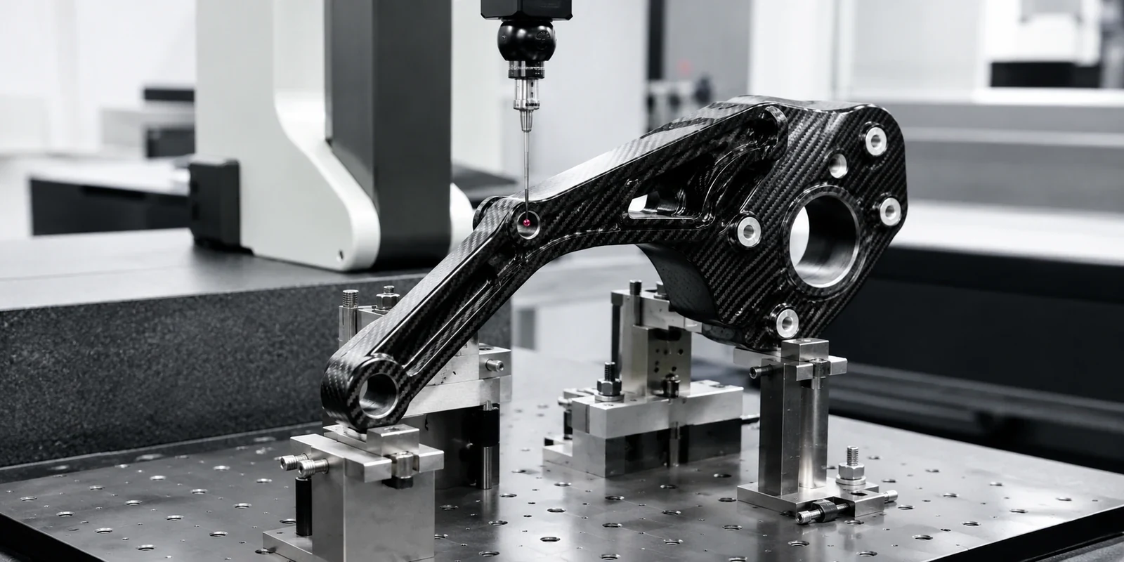
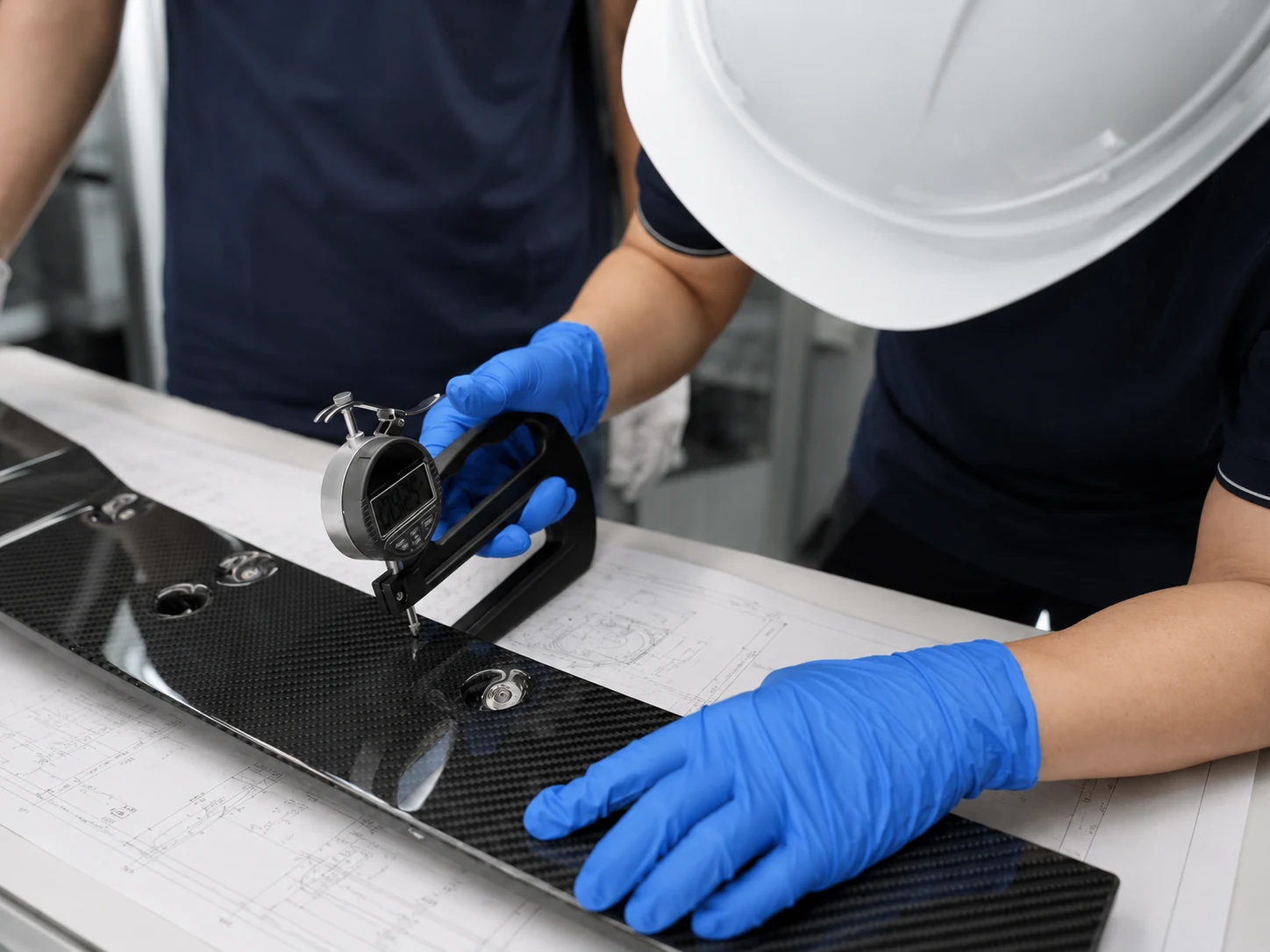
We organize what your team needs to approve into dimensions and interfaces, material or structural targets, visible surfaces, inspection or testing, and documentation. Critical datums, holes, inserts, thickness, weight, fit, finish and sampling details are then tied to the drawing and measurement method.
This gives production and quality teams the same practical reference for checking the part.
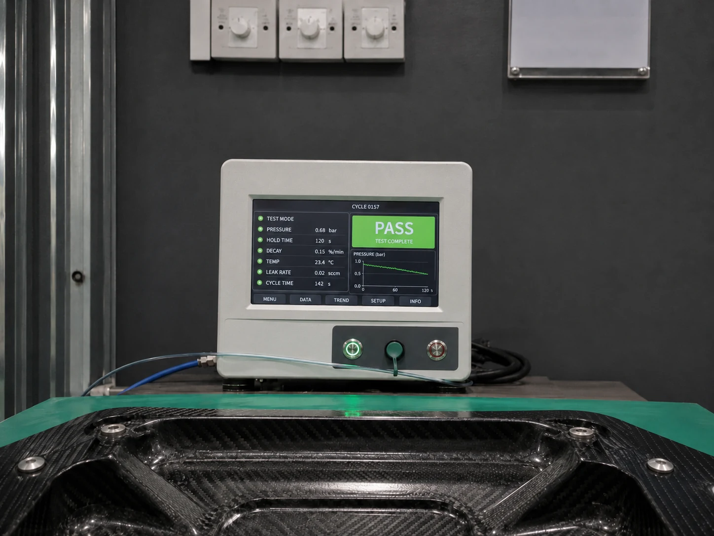
Use Controls That Match the Part and Its Risk
Available checkpoints cover incoming material and batch, tooling, layup, vacuum, cure, first article, in-process work, CNC features, surface, NDT where applicable, final inspection and packing.
We select the controls that matter for the project and connect them to the agreed drawing and quality plan. Your team can see where a critical characteristic is checked instead of receiving a generic quality statement.
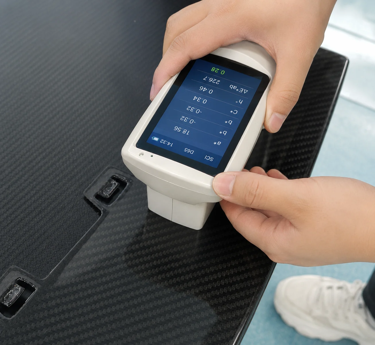
Choose an Inspection Method That Can Support the Decision
Available methods include dimensional inspection, CMM, surface checks, thickness and weight checks, C-scan for agreed internal-condition assessment, and mechanical or environmental testing where needed.
We confirm the method, sensitivity, sampling and approval criteria for the characteristics being checked. C-scan or another test is included when it belongs in the agreed quality plan.
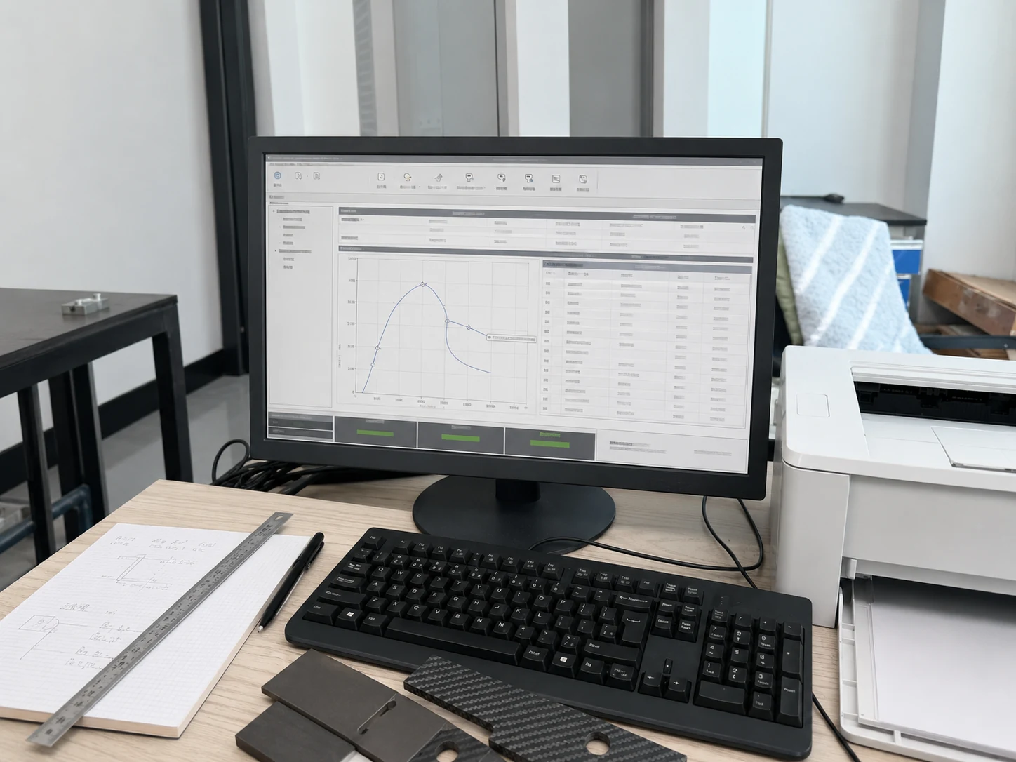
Confirm the Reports Your Team Needs
Project documentation may include material and batch information, layup travelers, vacuum records, cure charts, first-article or dimensional results, NDT or test results, nonconformance actions, final inspection and packing checks.
Tell us before quotation which documents your team needs for approval. We can then include the inspection, reporting and final checks in the proposed work.
08 · INDUSTRY ROUTES
Choose an Industry Route by theConditions Your Part Must Meet
Within each industry, what the part needs to do—not the industry label alone—guides the manufacturing and validation approach. Choose the closest application to show us the interfaces, environment and approval conditions that matter.
 01
01ROUTE 01
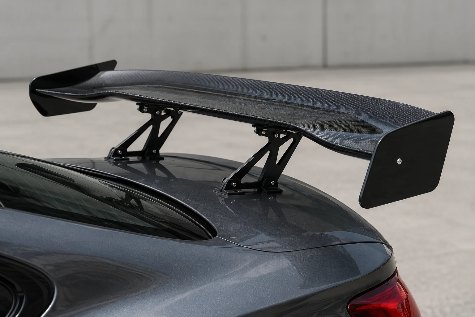
Automotive
Fitment, visible surfaces, vehicle interfaces, weight and stiffness often shape the work.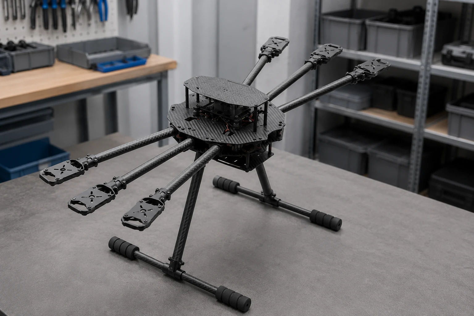 02
02ROUTE 02
Drone and UAV
Weight, vibration, plate and tube interfaces, variant control and assembly are common priorities.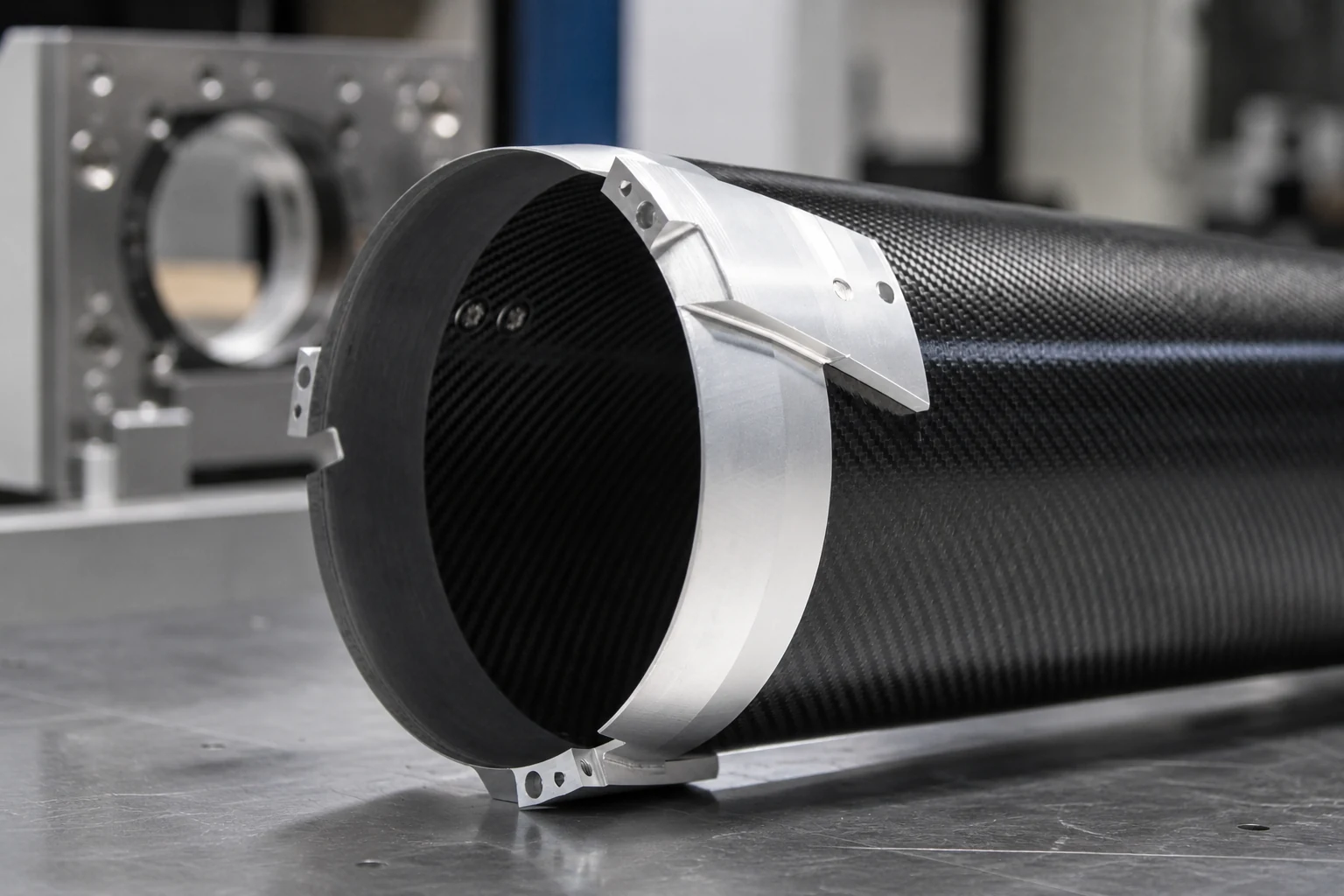 03
03ROUTE 03
Industrial equipment
Motion mass, dimensional stability, ESD or clean-environment conditions may affect design and verification.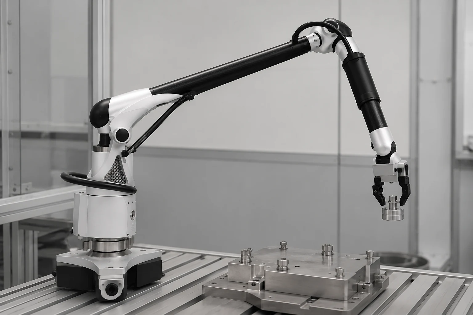 04
04ROUTE 04
Robotics
Inertia, stiffness, fatigue, cable routing and end-effector interfaces can guide the part definition.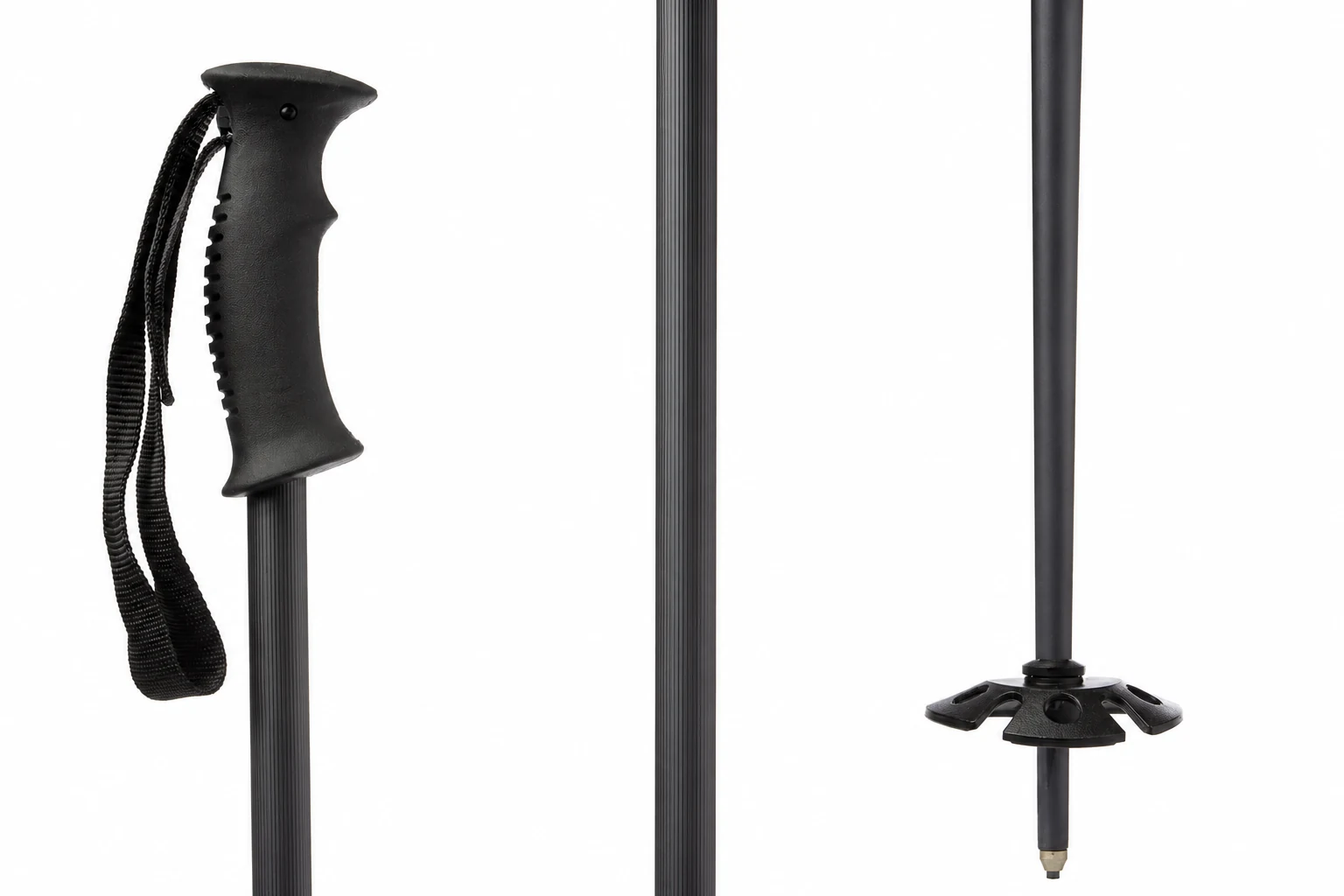 05
05ROUTE 05
Sports equipment
Load, impact, feel, appearance, repeated use and product-specific testing need separate consideration.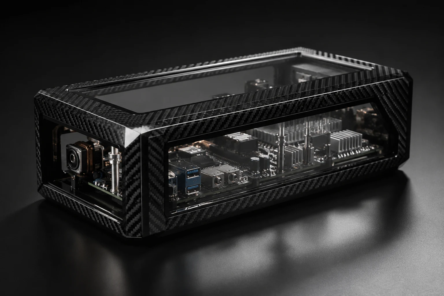 06
06ROUTE 06
Energy equipment
Environment, structural duty, insulation or conductivity and service access may affect the project. 07
07ROUTE 07
Aerospace-related
Customer drawings, material requirements, testing plans and documentation guide the work.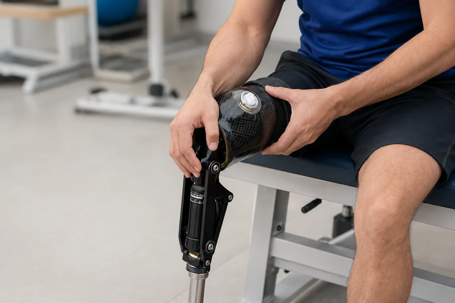 08
08ROUTE 08
Medical-related
Customer requirements and applicable third-party testing guide the manufacturing and documentation plan.NEXWAVE supports regulated and high-requirement projects through customer-defined drawings, testing plans and documentation. Management-system certification and manufacturing support do not constitute product certification or regulatory approval.
SELECTED PROJECT PROOF
Different Requirements, Different Manufacturing Approaches
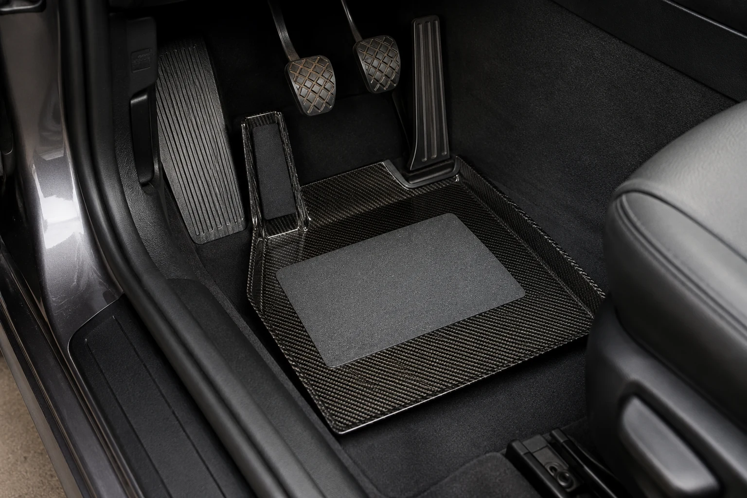
BMW E46 Foot Tray
- Application
- Automotive interior component.
- Market
- Poland.
- Challenge
- Turn an approved geometry and finish route into repeatable supply.
- Manufacturing focus
- Autoclave production, downstream finishing and repeat-order continuity.
- Project status
- Real order, customer feedback and repeat purchase.
NEXWAVE produced an autoclave-molded carbon-fiber foot tray for a customer in Poland, with fit and visible-surface quality central to approval. The completed order led to a repeat purchase.
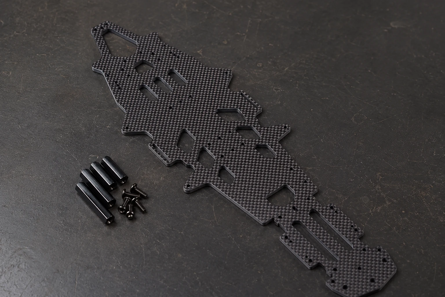
UAV Frame Plate
- Application
- Industrial UAV structures across 21 variants.
- Challenge
- Maintain hole positions, version control and repeatability across similar products.
- Manufacturing focus
- CNC production and controlled variant management.
- Project status
- More than 500 pieces per month.
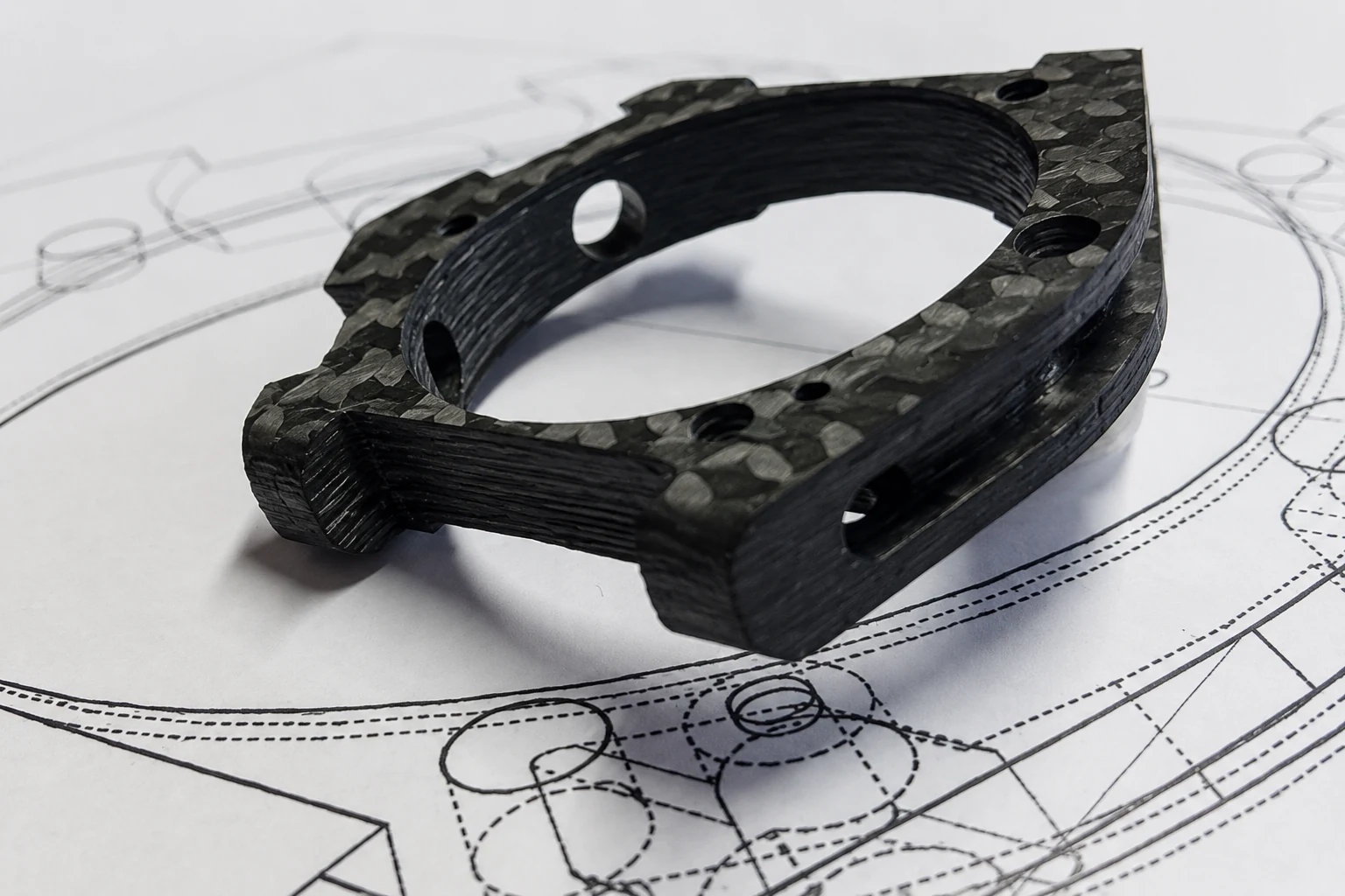
CNC machining and clear variant control supported production of more than 500 carbon-fiber frame plates per month across 21 variants.
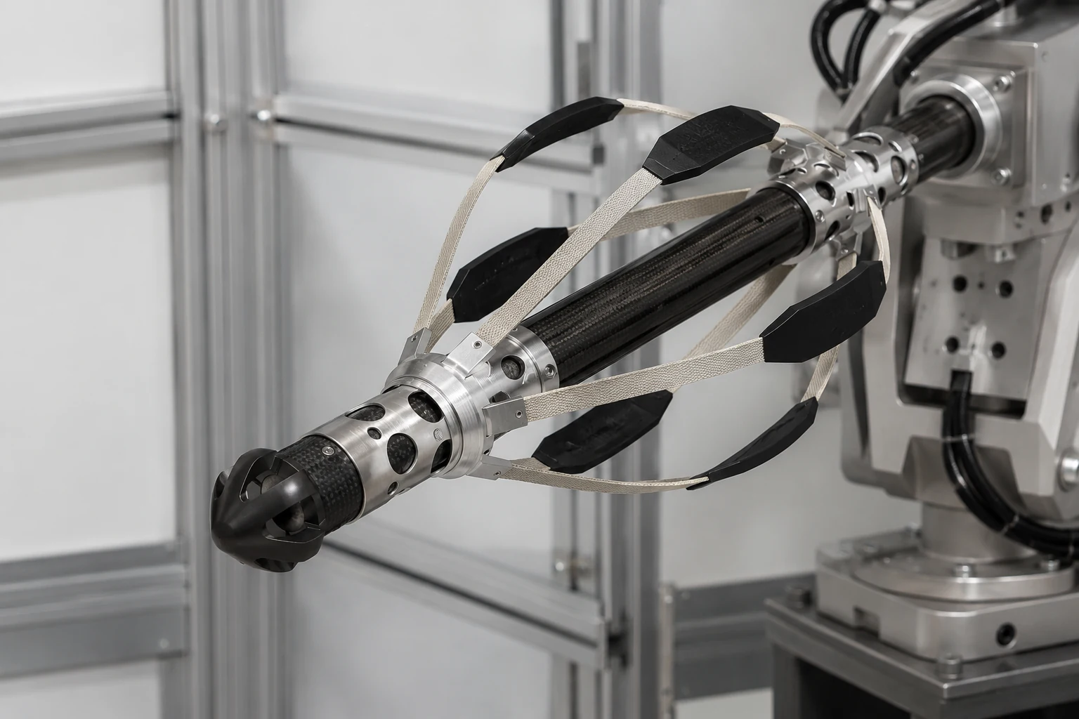
Robotic End Effector
- Application
- Robotics and industrial automation.
- Challenge
- Coordinate geometry, stiffness, moving mass and connected interfaces.
- Manufacturing focus
- Custom molding around system requirements and hardware integration.
- Project status
- Approved project example; no broader performance claim is implied.
Custom molding produced the required composite form while the interface and assembly needs were reviewed with the surrounding system.
09 · FACTORY + GLOBAL DELIVERY
A Carbon Fiber Factory That ConnectsEngineering, Production, andGlobal Delivery
Supplier due diligence becomes more useful when company facts show how your project will move through engineering, production, quality and delivery.
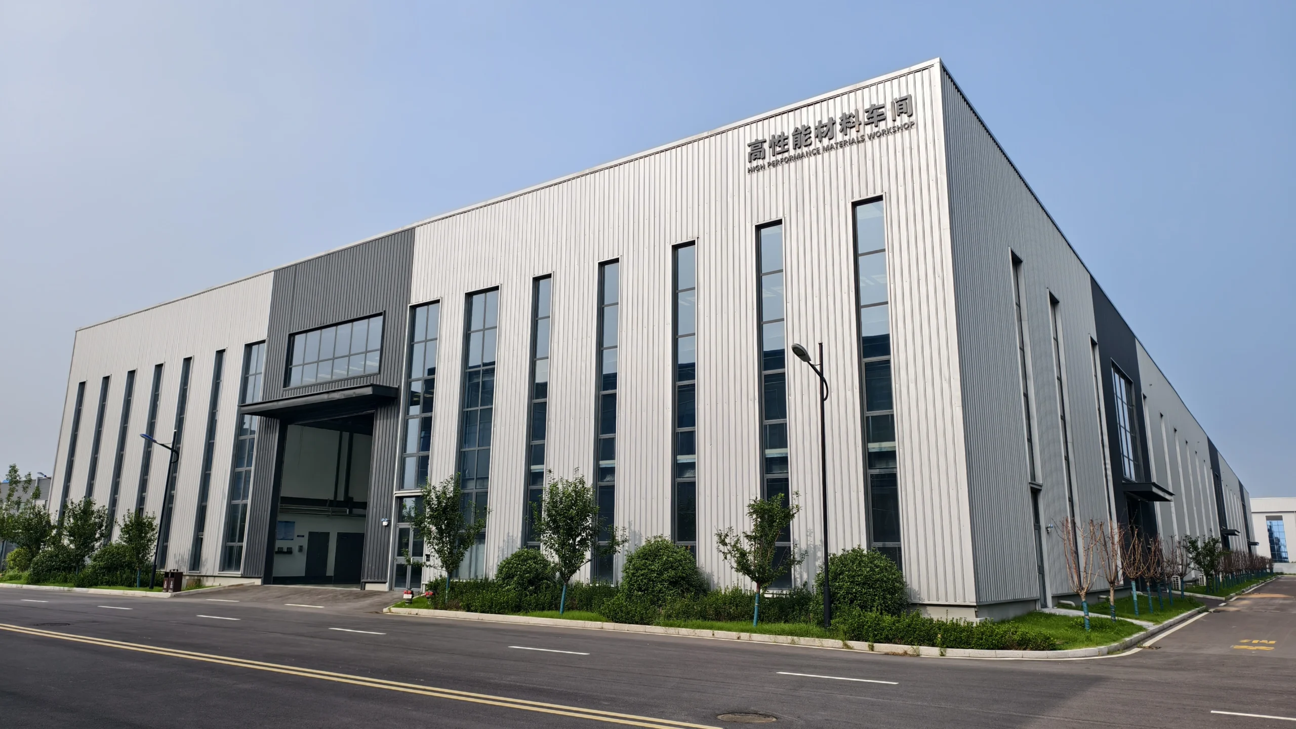
NEXWAVE’s factory is in Tengzhou, Zaozhuang, Shandong, China. The site covers 80 mu, approximately 53,333 m², with 30,000 m² of buildings and 26,000 m² of production area.
The company was established in 2020, and the factory entered production in 2021. Development through 2024 brought material preparation, forming, machining, inspection and technical teams into the same manufacturing organization.
NEXWAVE has more than 80 employees, including 30+ composite design engineers, 6 process engineers and an 8-person quality team. This gives projects a more direct handoff from design review into production planning and order-specific inspection.
In 2024, annual carbon-fiber procurement reached 3,000 tonnes, with long-term agreements established with Toray, Toho and Mitsubishi. These relationships support material planning for manufacturing programs. NEXWAVE’s role is downstream material processing and part manufacturing rather than precursor production or fiber spinning.
For your team, the practical value is direct coordination among engineering, process, production and quality. We help you confirm whether the available material, manufacturing, inspection and delivery approach fits the project.
PLAN BEFORE PACKING
Plan International Orders Before Packing Begins
NEXWAVE serves countries across Europe, North America, Asia, Oceania and the Middle East through exports coordinated from its manufacturing base in China.
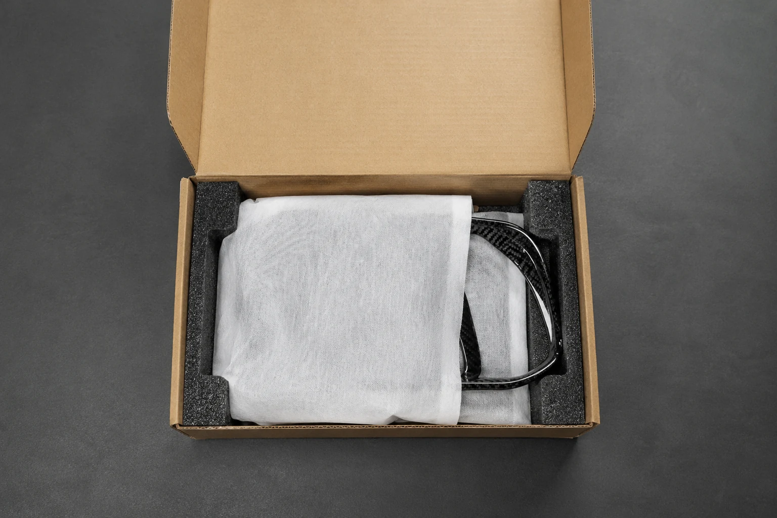
We align packaging, product and batch labels, shipment documents, logistics inputs and export review with the part, transport method, destination, Incoterm, end use and customer requirements. Foam, separators, crates, edge protection and visible-surface protection can be planned around part size and transport risk.
Confirming these details early helps reduce last-minute packing changes, surface damage and unexpected freight handling, especially for long parts, fragile edges and visible carbon-fiber surfaces.
10 · CONDITIONS + EXCEPTIONS
Clarify the Conditions That AffectReview, Quotation, and Delivery
Four conditions shape how the first review becomes a formal quotation and an executable delivery plan.
01Can NEXWAVE Accept Customer-Specified Materials, Suppliers, or Test Standards?+
Yes, they can be reviewed. Share controlled materials, approved sources and test standards early so we can check availability, traceability, process compatibility and the required specimen, conditioning, method and report before quotation.
CONDITION 01 / REVIEW BEFORE QUOTATION02Is a Project Review the Same as a Formal Quotation?+
No. A project review identifies fit, missing information, a likely manufacturing approach and the next decision. A formal quotation follows when material, geometry, quantity, inspection, appearance, capacity and trade inputs are clear enough to price and schedule.
CONDITION 02 / REVIEW BEFORE QUOTATION03How Should Sensitive or Oversized CAD Files Be Submitted?+
Raise NDA or confidentiality requirements before sending sensitive information. Files can be sent through the project form, email or direct CAD upload. For files over 100 MB, provide a controlled cloud link and identify the version, assembly context and access expiry.
CONDITION 03 / REVIEW BEFORE QUOTATION04When Should Special Packaging or Trade-Document Requirements Be Confirmed?+
Confirm them before quotation or manufacturing approval whenever they affect packing design, handling, cost, timing or destination acceptance. Share the destination, Incoterm, transport method, labeling rules, document requirements and any special protection for visible surfaces, long parts or sensitive edges.
CONDITION 04 / REVIEW BEFORE QUOTATION11 · PROJECT INTAKE
Start a Project Review with theInformation You Already Have
You do not need a finished technical package to begin. Send enough information for us to understand who you are, what the part or product is and where the project stands.
Minimum Information
- Your name, company and email.
- Product or part type.
- Estimated quantity or current stage.
- The best available drawing, sample, photograph or target description.
Information That Helps Us Give You a Clearer Answer
- Intended use and service environment.
- Material or performance target.
- Critical dimensions, interfaces and visible-surface expectations.
- Inspection, testing or documentation needs.
- Target timing, destination and Incoterm.
- Budget or target-price context when available.
Where relevant, the quotation separates tooling, sample, part, finishing, packing and shipping inputs. This helps your team see which costs are one-time, which repeat with each order and what changes the total.
What Happens After Submission
- 24hNEXWAVE sends confirmation.
- 48hIf information is missing, we provide a missing-information list when needed.
- 3–5dThe engineering team completes manufacturability and process review and provides a preliminary manufacturing recommendation and quotation when the available information supports it.
This gives your team a clear next step. Tooling, quality, commercial terms and delivery timing are then finalized with the project details.