
Turn a Carbon Fiber Design into a Part That Works, Fits and Can Be Repeated
NEXWAVE connects DFM, material and laminate review, tooling, forming, machining, inspection and delivery around the result your part must achieve.
Avoid the Problems That Turn a Carbon Fiber Part into Rework
Most carbon fiber manufacturing problems do not begin at final inspection. They begin when a drawing cannot be released from the tool, a load direction is missing, a mating part was never reviewed, or nobody defined what the approved surface should look like.
The practical goal is simple: catch the decision while it is still a drawing, a route or a tool concept, not after material, machining and finishing have already been added to the part.
What this protects
for your project
A part that can actually be made.
Geometry, material form, release direction, tooling and downstream access are reviewed together before the affected tool or production route is approved.
A part that fits where it belongs.
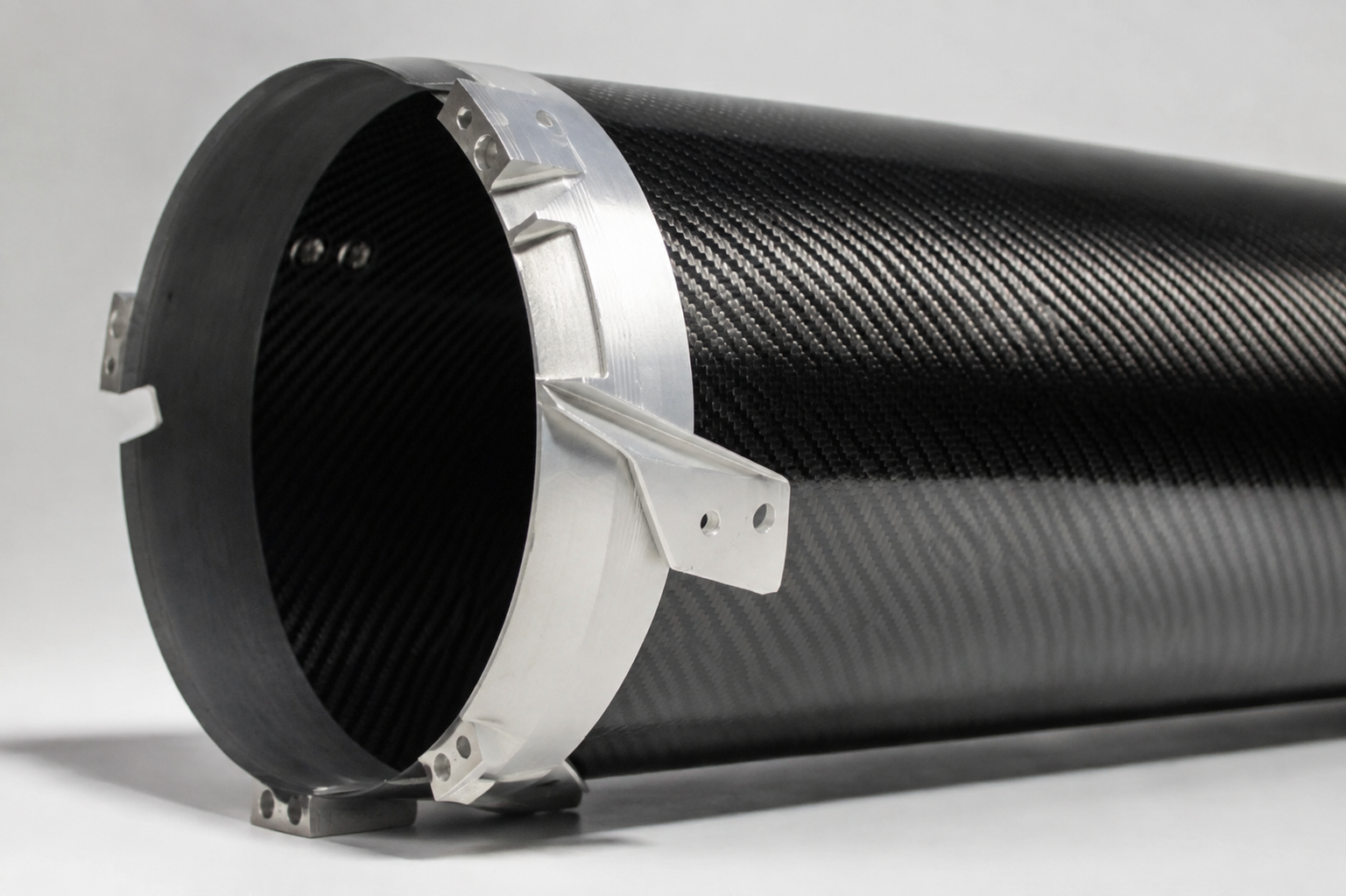
Functional datums, holes, edges, inserts, bonded interfaces and mating context are carried into machining and assembly checks.
A part that can pass the agreed checks.
Internal condition, dimensions, visible surfaces and records are connected to the drawing, approved sample or project quality plan.
An order that can be repeated.
The accepted material, tool, program, drawing, inspection and delivered state become a controlled reference for later batches.
Five risks worth finding early
| What can go wrong | What the customer sees later | What NEXWAVE does before more cost is added | State |
|---|---|---|---|
| The geometry does not suit the intended route | Tool changes, a delayed sample or a part that cannot be released without damage | Reviews release direction, tool split, access, laminate handling and process fit during DFM | HOLD |
| The part does not meet the agreed internal, dimensional or surface condition | A held batch, rework, remake or an approval dispute | Connects each critical requirement to an applicable process control, inspection method and approval source | HOLD |
| Holes, edges, inserts or mating interfaces do not line up | Field drilling, shimming, interference or a part that cannot be installed | Establishes the datum and mating context before tooling, CNC programming or assembly work | HOLD |
| The first article passes but later batches drift | A repeat order no longer matches the approved sample or drawing state | Freezes the approved manufacturing and delivered-state baseline and identifies change triggers | HOLD |
| The assembly context is missing | A dimensionally conforming single part still fails in the complete system | Requests mating-part data, fasteners, access, installation sequence and the required fit-check method | HOLD |
These are manufacturing problems, not paperwork problems. The information request exists to prevent one of these outcomes, and each open item should have a named owner and a clear effect on the proposed solution.
Make the Part Manufacturable Before Tooling Locks the Problem In
A CAD model can be complete and still be expensive or impractical to manufacture in carbon fiber.
Vertical walls may trap the part on the tool. A sharp internal corner may be unreachable by the tool or CNC cutter. A deep cavity may be difficult to compact. A tolerance applied to every surface may add inspection and machining work without improving how the part functions.
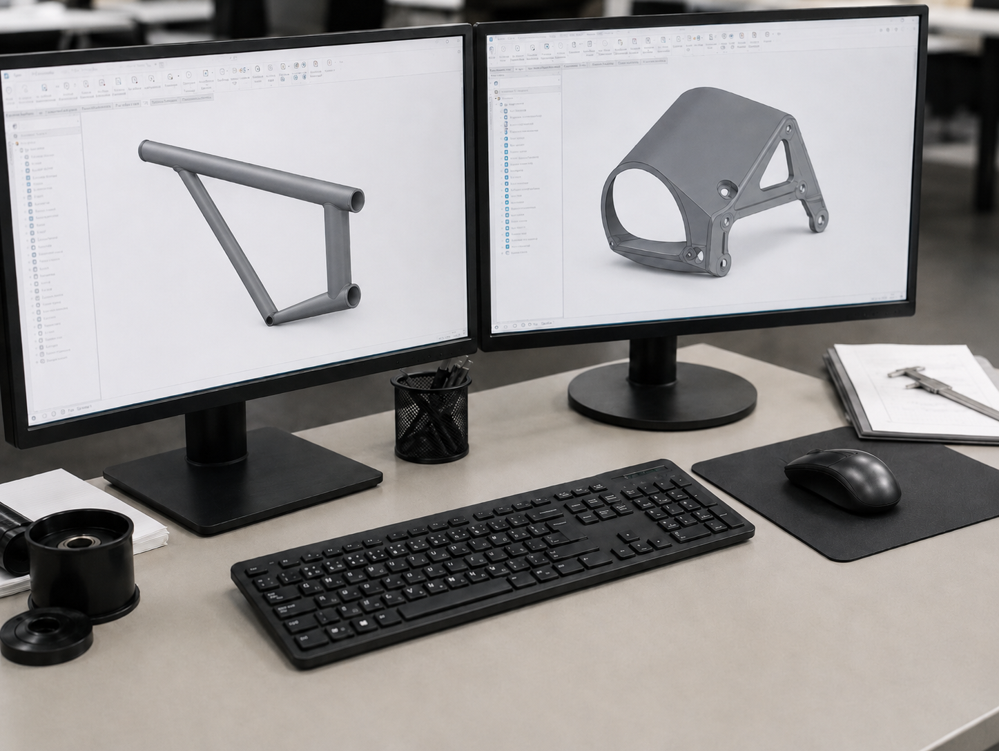
NEXWAVE uses a multi-role DFM review to turn these issues into specific changes before the affected tool, program or sample is released.
What the review checks
The project engineer leads the review and brings in process, tooling, Quality and CNC programming engineers when the part requires them. The team checks:
tool release, split lines, undercuts and access for layup or charge placement;
radius, depth, wall and laminate transitions that can create bridging, distortion or machining risk;
functional datums, critical dimensions, holes, edges, inserts and mating interfaces;
visible faces, weave direction and the surface that should come from the tool;
inspection access and the condition in which a critical feature will be measured;
whether the material, laminate, forming route and proposed quantity stage belong together.
SIGN-OFF — PROJECT ENGINEER CONSOLIDATES · TECHNICAL MANAGER APPROVES BEFORE ISSUE
What you can receive from DFM
Depending on the assigned engineering scope, the review may return
marked 2D drawings, annotated or revised 3D data, a DFM issue list,
tool split and release-direction suggestions, datum or interface views,
a preliminary material/laminate/forming direction, risk priorities
and the items that require customer approval.
The point is not to give you a generic checklist. It is to show which feature creates which manufacturing consequence and what must change before the next commitment.
A manufacturing case with the responsibility kept clear
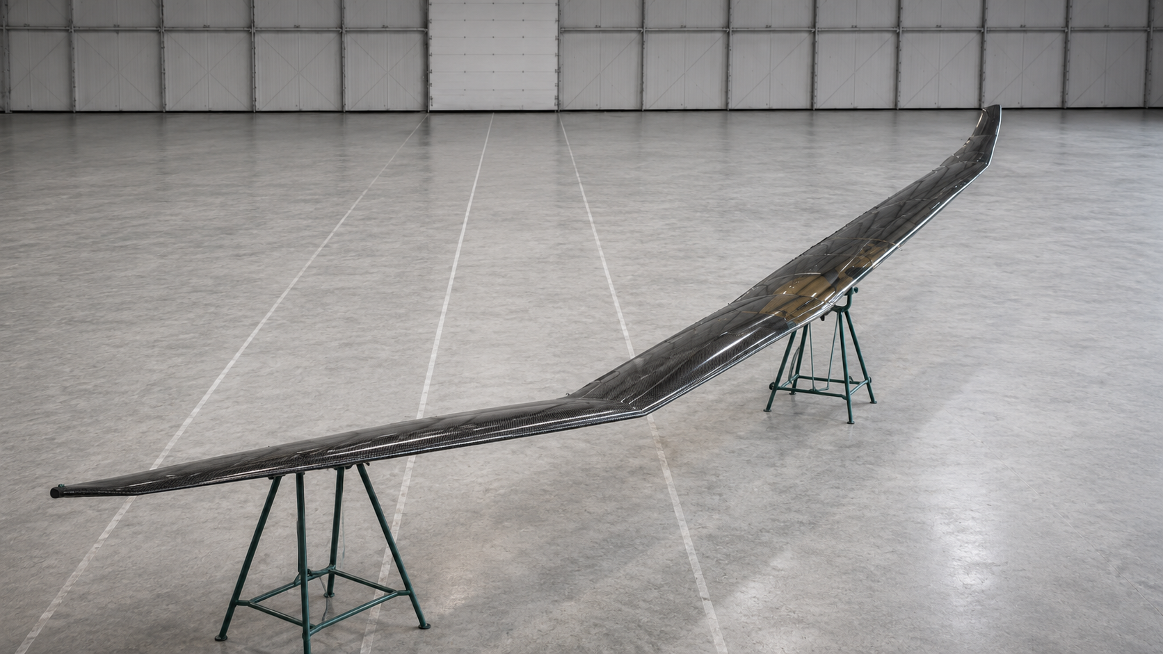
For project P-2026-038, NEXWAVE manufactured, machined and verified an unmanned-aircraft structural part from the customer's supplied laminate schedule and material specification.
This is evidence of manufacturing execution and verification under that project's requirements. The customer retained the laminate definition, test interpretation and final structural approval.
Build the Part Around the Load and Environment, Not a Carbon Fiber Label
“Use carbon fiber” is not a complete material decision.
A woven cosmetic shell, a torsion-loaded tube and a fatigue-loaded bracket can all be carbon fiber parts, but they do not need the same fiber direction, resin system, laminate or test plan.
START WITH WHAT THE PART MUST DO
the main load direction and whether the part sees tension, compression, bending, torsion, impact or repeated cycles;
operating and storage temperature;
moisture, UV, saltwater, fuel, oil, solvent or other chemical exposure;
the metal, adhesive, fastener, seal or moving part it must interface with;
the visible-surface requirement and any weight, stiffness or life target;
the drawing, customer test or qualified authority that will approve the result.
What NEXWAVE can decide and what remains with the customer
| Engineering task | NEXWAVE role | Approval boundary |
|---|---|---|
| Fiber-direction recommendation | Project and process engineers may propose directions around the stated load path | Customer confirms the governing loads and approves the released definition |
| Material and resin-system direction | Project and material engineers may compare reinforcement form, resin compatibility and service conditions | Final material approval follows the assigned project Scope |
| Laminate-schedule direction | Process engineers may develop or refine a proposed schedule using layup software and internal rules | Customer or named design authority approves the released laminate where required |
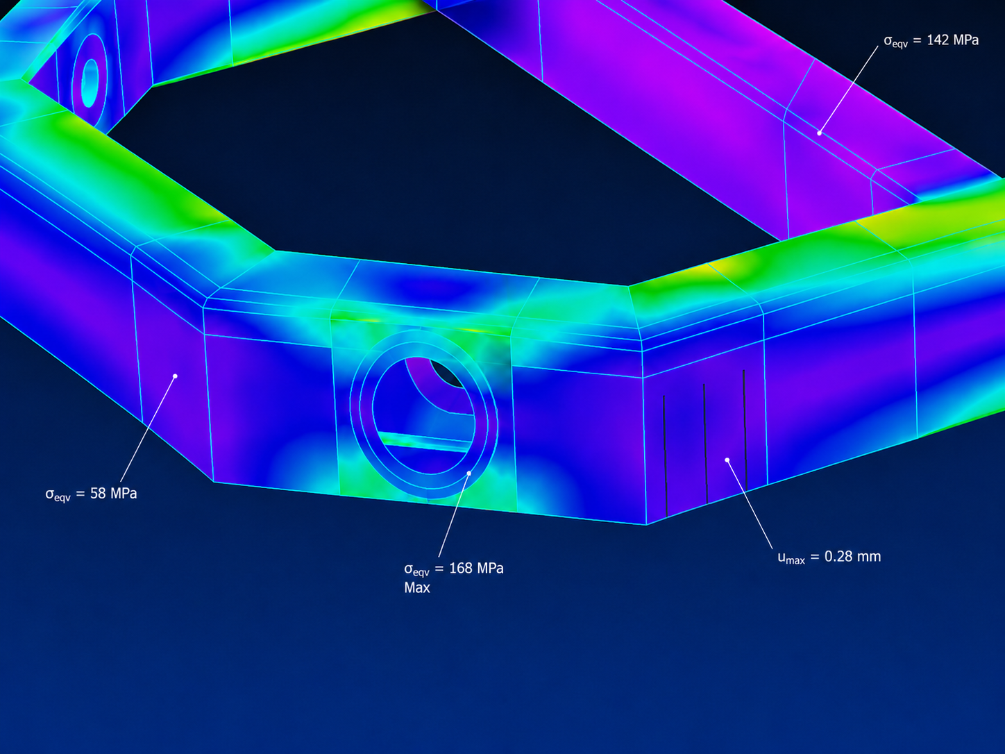
| CLT or hand screening | Structural engineers may use internal Excel tools and classical laminate theory within the assigned Scope | It is screening support, not final product certification |
| FEA support | NEXWAVE may provide Engineering Constants and coordinate a customer, customer-appointed or NEXWAVE-recommended third party | The customer or designated qualified third party owns analysis approval and final structural approval |
| Witness coupons or test planning | Process and Quality engineers may define project-relevant specimens and evidence with the customer | The governing specification and approval authority control the final plan |
This division prevents two opposite mistakes: selecting a material because its name sounds stronger, or allowing a manufacturer to imply structural authority it was never assigned. The buyer gets a construction direction tied to the real service condition and a clear list of what still needs analysis, testing or approval.
Choose the Forming Route and Tooling as One Solution
The right process is the one that can form the geometry, hold the required surfaces and datums, release the part, support the expected production stage and hand the part into machining, inspection or assembly. A machine name alone cannot answer those questions.
SCREENING — SIX ROUTE FAMILIES
Prepreg + autoclave
- Often considered when
- Complex laminates, changing thickness, large or curved forms and project-selected internal-condition evidence matter
- What can change or reject the route
- The complete part/tool load does not fit the usable zone, the bag-side surface is unacceptable, or access and compaction are not practical
- Tooling question that must be answered
- Tool material and thermal behavior, vacuum-bag seal, thermocouple plan, release and support
Hot press / compression molding
- Often considered when
- Matched tooling, repeat geometry, controlled opposing surfaces or a repeat-production route is needed
- What can change or reject the route
- Deep returns, difficult release, unstable charge/laminate distribution or a tool footprint that does not suit the applicable press
- Tooling question that must be answered
- Split line, ejection, heating/cooling, projected area and required unit pressure
Forged-carbon compression
- Often considered when
- A complex three-dimensional form can use a discontinuous-fiber charge and the material architecture suits the load
- What can change or reject the route
- Continuous load paths, specified reinforcement orientation or a different structural architecture is required
- Tooling question that must be answered
- Charge placement, flow, split/ejection and visible-surface behavior
Filament winding
- Often considered when
- A rotational part needs controlled hoop or helical reinforcement
- What can change or reject the route
- The shape is not windable, end features interrupt the path or later machining cannot be supported
- Tooling question that must be answered
- Mandrel, removal, winding program, tension and cure support
Tube rolling
- Often considered when
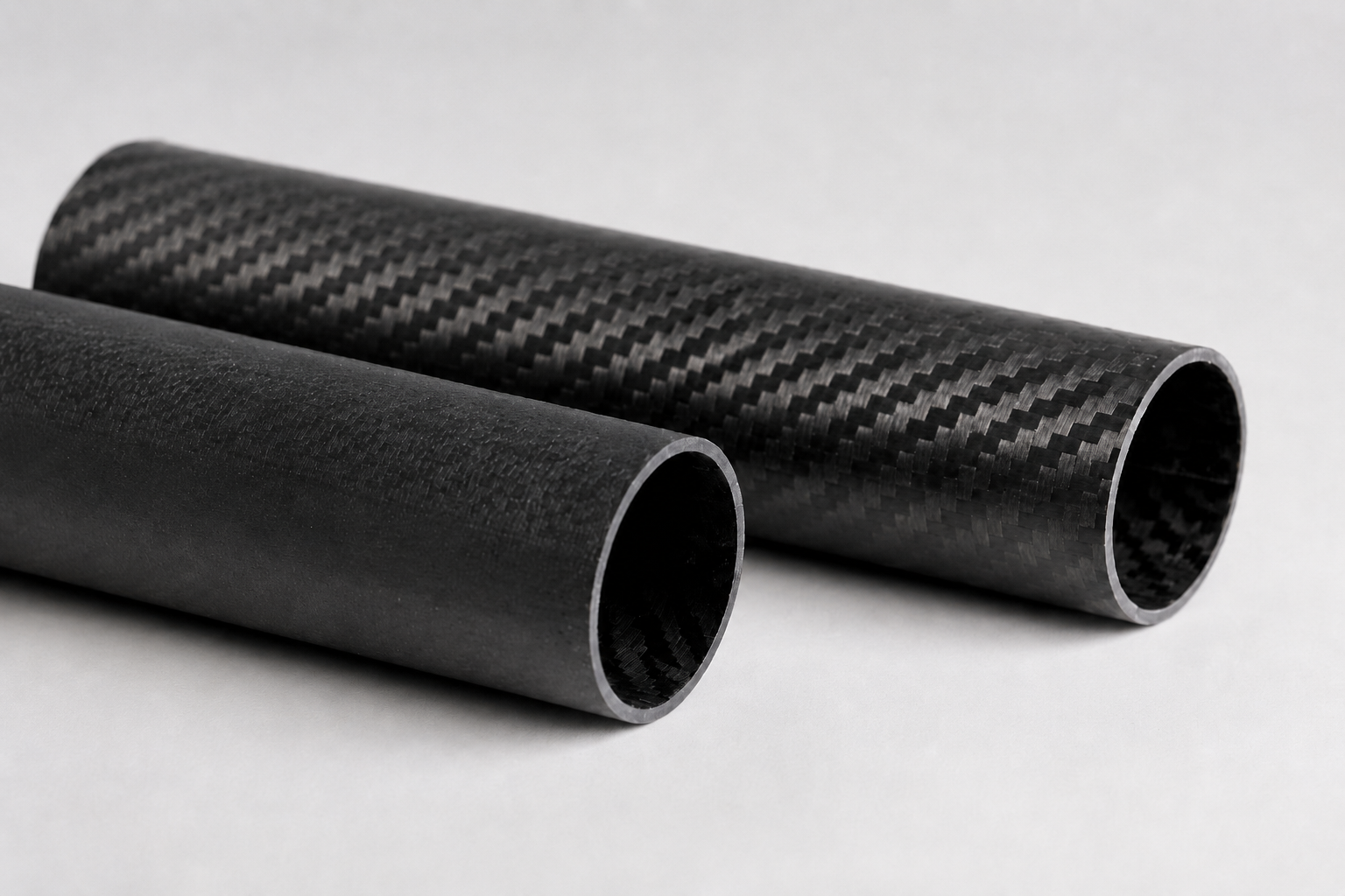
- A tube needs continuous longitudinal reinforcement with a rolled laminate construction
- What can change or reject the route
- Section, wall build-up, inner-surface or end-feature requirements do not suit the method
- Tooling question that must be answered
- Mandrel, ply placement, overlap, compaction and cure
RTM / liquid infusion
- Often considered when
- Dry reinforcement, resin flow and closed- or vacuum-assisted tooling may suit the part and production objective
- What can change or reject the route
- Flow path, permeability, resin system, geometry, finish, validation or responsibility boundary does not support the route
- Tooling question that must be answered
- Preform, resin inlet/vent, seal, flow verification and tool responsibility
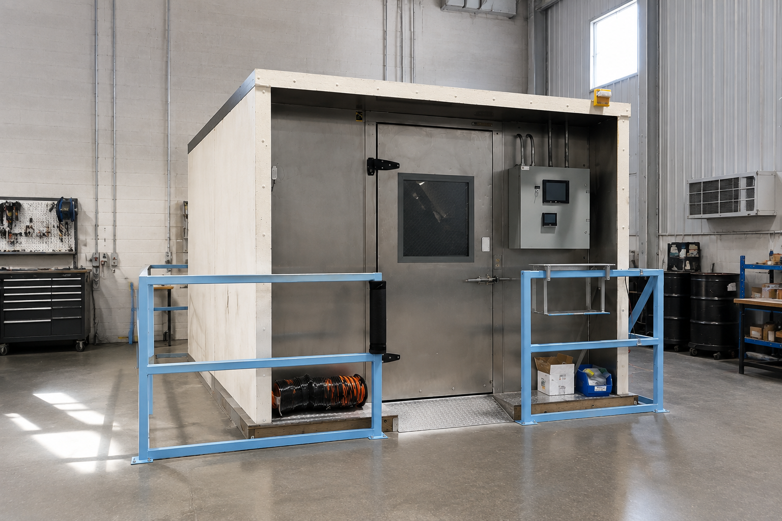
NEXWAVE currently operates five same-specification autoclaves with an approximately φ1600 × 3800 mm usable working zone, five 2500-ton-class hot presses, two forged-carbon presses, two filament-winding machines and one tube-rolling line.
NOTE — AUTOCLAVE VALUE IS A PRACTICAL PART-AND-TOOL PLANNING ENVELOPE, NOT THE CHAMBER NAMEPLATE · PRESS RATING IS NOMINAL CLAMPING FORCE, NOT TABLE SIZE · EVERY TOOL STILL REQUIRES A PROJECT FIT CHECK
Pultrusion is not part of the current in-house forming scope. If a continuous-profile requirement points toward pultrusion, the review must define the external sourcing and responsibility boundary or identify whether another supported route fits the part.
Stop Hidden Defects and Process Drift Before Final Inspection
Some composite problems are obvious when the part leaves the tool. Others stay hidden until machining, assembly or service. Waiting for final inspection means the material, labor and downstream work are already inside the part.
The useful control question is not “Do you inspect quality?” It is “What can fail on this route, where can it first be found, what stops the affected work, and what record shows what happened?”
ROUTE-SPECIFIC CONTROL MAP
Prepreg + autoclave
ROUTE 01- Failure conditions to watch
- Wrong ply sequence or orientation, bridging, bag leakage, cure departure, delamination or porosity indication
- Earliest useful control
- Material-status check, ply verification, bag and thermocouple review, run monitoring, post-cure inspection
- Evidence and limitation
- Traveler and cure/vacuum record; C-scan where geometry, thickness, coupling and defect type make it suitable
Compression / forged carbon
ROUTE 02- Failure conditions to watch
- Wrong charge or placement, uneven flow, incomplete fill, pinholes, delamination, distortion or surface departure
- Earliest useful control
- Charge/layup confirmation, mold condition, controlled closing/cure state and inspection after release
- Evidence and limitation
- Process record, weight/dimensional/surface evidence and project-selected NDT where applicable
Filament winding / tube rolling
ROUTE 03- Failure conditions to watch
- Fiber-angle or tension departure, gap/overlap, wall variation, diameter/straightness or end-condition problem
- Earliest useful control
- Program and material verification, in-process angle/tension observation and post-cure dimensional checks
- Evidence and limitation
- Process/program record, wall/diameter/straightness evidence and NDT only where the part and defect support it
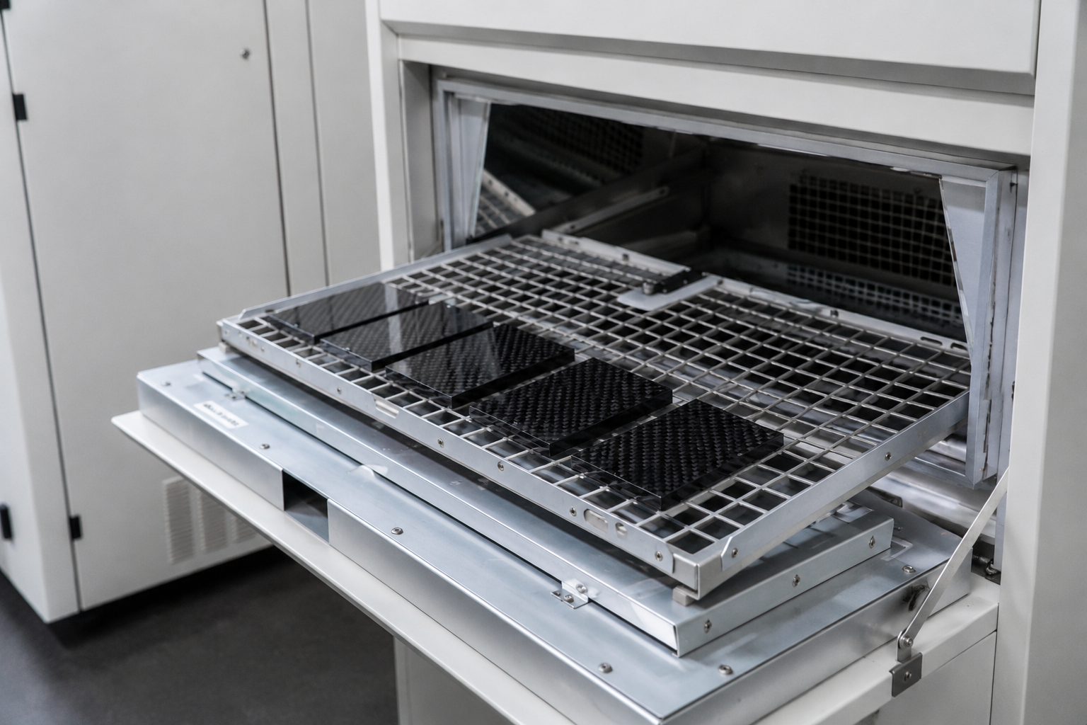
C-scan is useful for applicable delamination and porosity indications. It is not a universal answer. Complex curves, deep cavities, small radii, very thin or thick laminates, high-attenuation materials and defects that do not present well to the beam may require another method or a bounded coverage statement in the quality plan.
What happened when a batch did not pass
SIGNATURE — BATCH 120 · JULY 2026In July 2026, final inspection stopped a 120-part molded batch after 47 parts exceeded the project's pinhole limit. The affected parts were identified and isolated before shipment. Under NCR-2026-047 and CAR-2026-022, 32 mildly affected parts followed a customer-approved repair, refinishing and 100% reinspection route; 15 severely affected parts were scrapped. The work instruction was updated with an added ply-count check before production continued.
That case does not promise a zero-defect process. It shows the result the buyer needs when a problem occurs: the affected scope is held, the customer controls the approval that belongs to it, repaired parts are checked again, and rejected parts do not quietly enter the shipment.
Carry the Required Fit Through Machining, Inserts, Bonding and Assembly
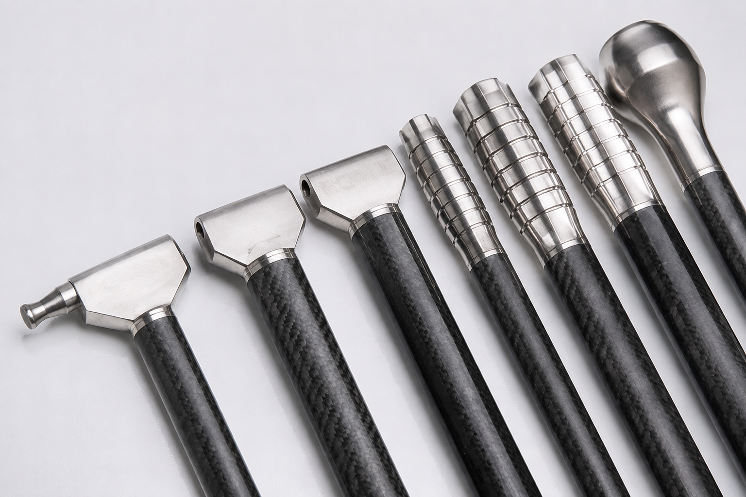
A molded shell can look correct and still fail in the customer's assembly. Holes may not line up. An edge can interfere. A metal insert can be positioned correctly on the drawing but wrong for the real mating part. A bonded joint can lack the preparation or support needed for the stated load.
NEXWAVE carries one functional datum chain from the tool into the downstream features:
the tool establishes the approved locating reference;
REF ESTABLISHED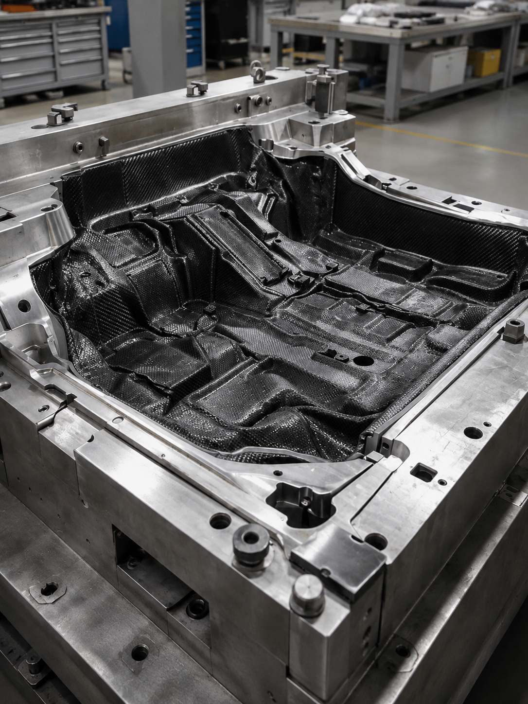
the formed part transfers that reference into a vacuum, mechanical or dedicated CNC fixture;
REF TRANSFERRED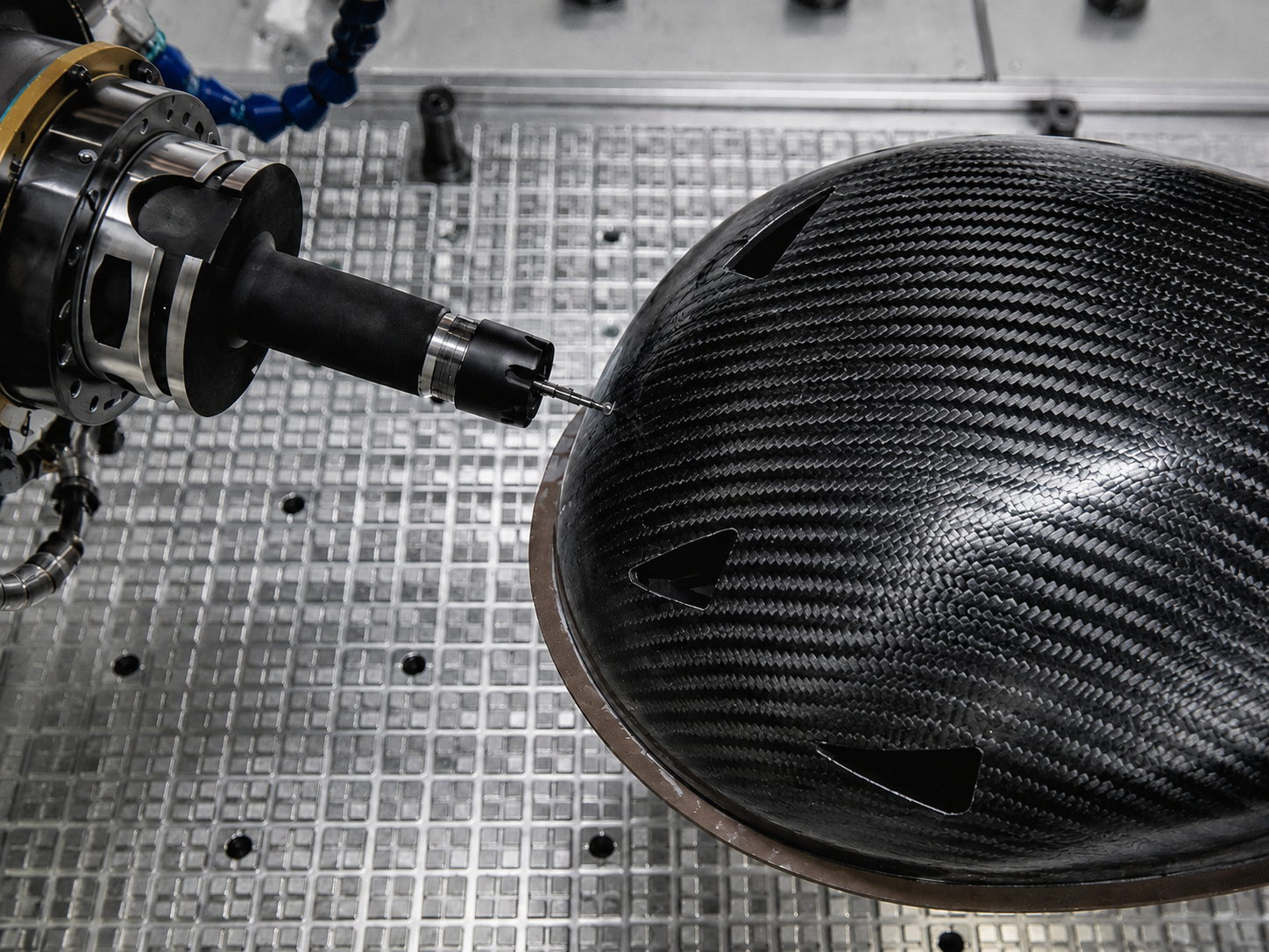
the controlled CNC program and revision create the required edges, holes and countersinks;
PROGRAM REV LOCKED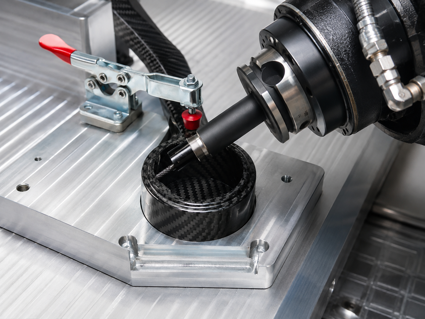
insert and bonding fixtures locate features to the same functional reference where applicable;
INTERFACE LOCATED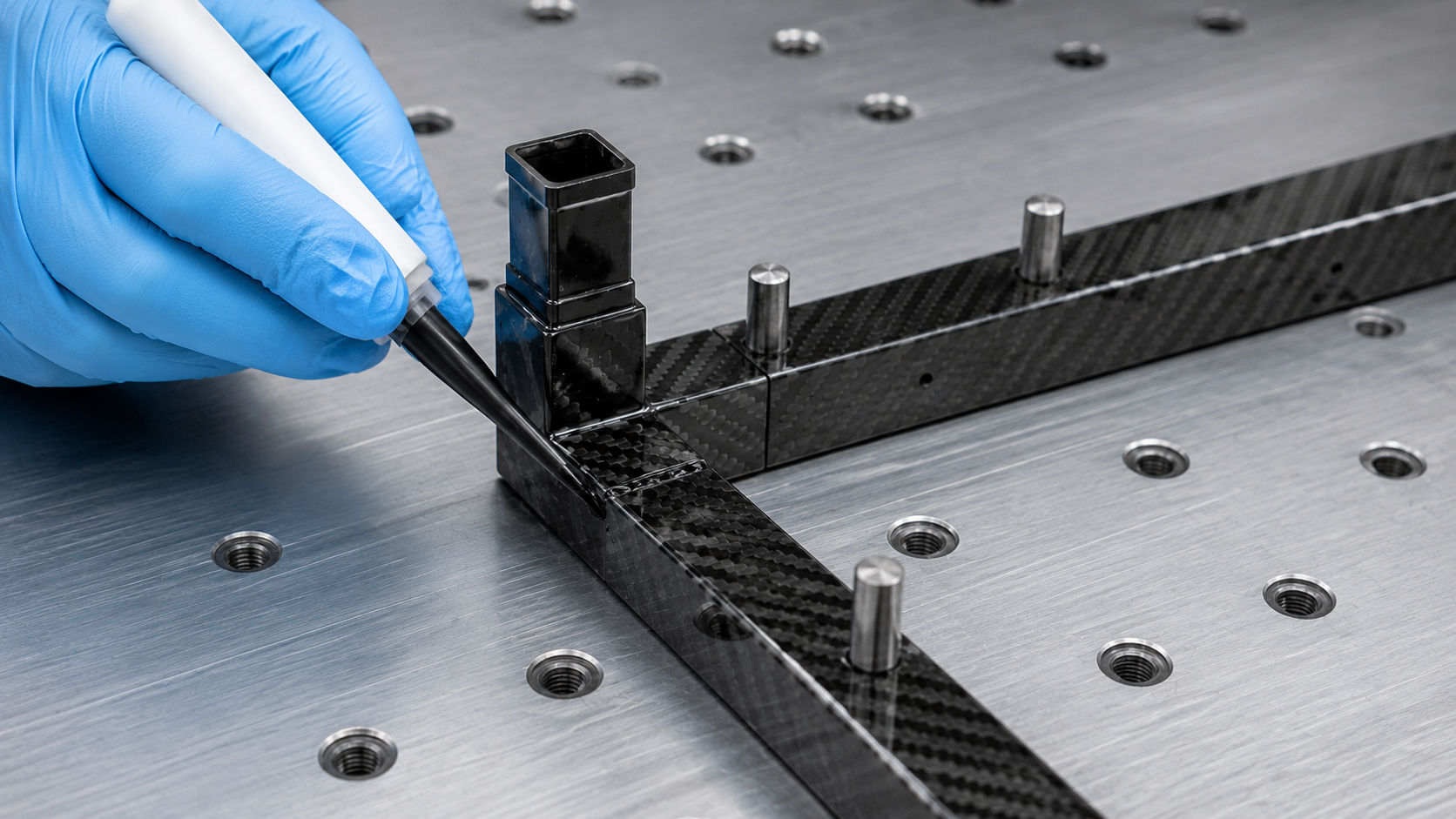
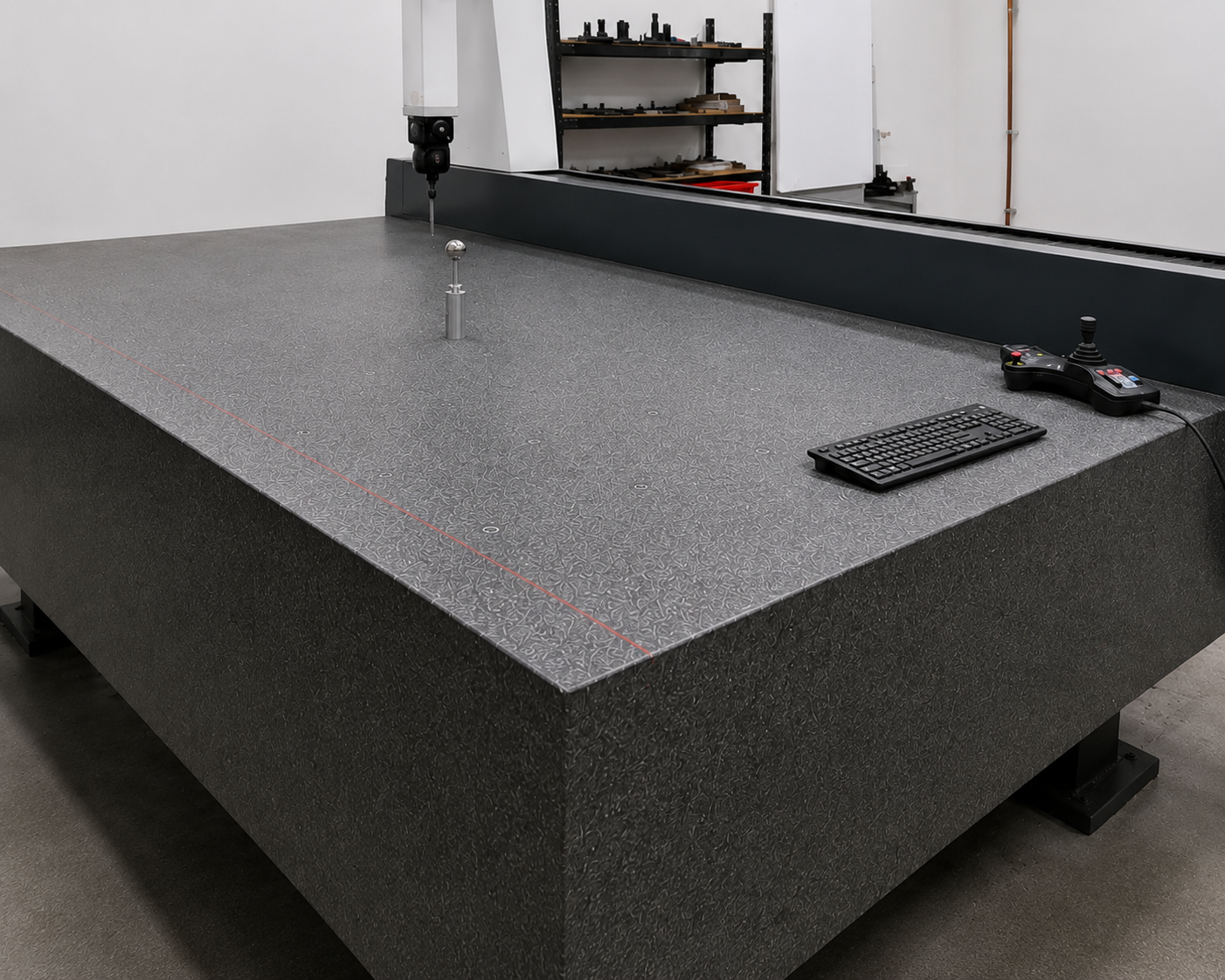
CMM, gauges or a physical mating check verify the condition in which the customer will use the part.
50/50 — NO INTERFERENCE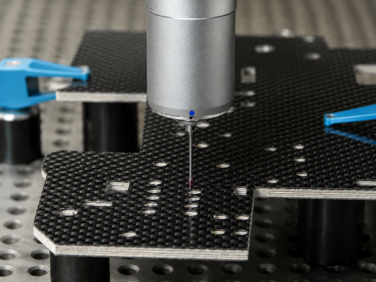
What must be known to promise fit
Provide the mating-part model or drawing, fastener specification, installation sequence, available tool access and the functional datum.
If those inputs are missing, NEXWAVE can verify the single part against its drawing, but it cannot turn that into an unsupported promise that the complete assembly will fit.
For P-2026-038, the customer supplied the laminate and material definition. NEXWAVE controlled manufacturing, five-axis machining and the agreed fit-verification route.
The outcome is a finished component presented in the agreed fit state, not a molded blank that leaves drilling, insert location or interface correction to the receiving team.
Protect the Visible Surface Until the Part Reaches the Customer
A structurally usable part can still be rejected because the weave is distorted, pinholes are visible, the gloss or color does not match, an edge is damaged or the finished surface was marked during handling. The surface must be defined before tooling and protected after inspection.
Turn “looks good” into an approval reference
NEXWAVE can combine:
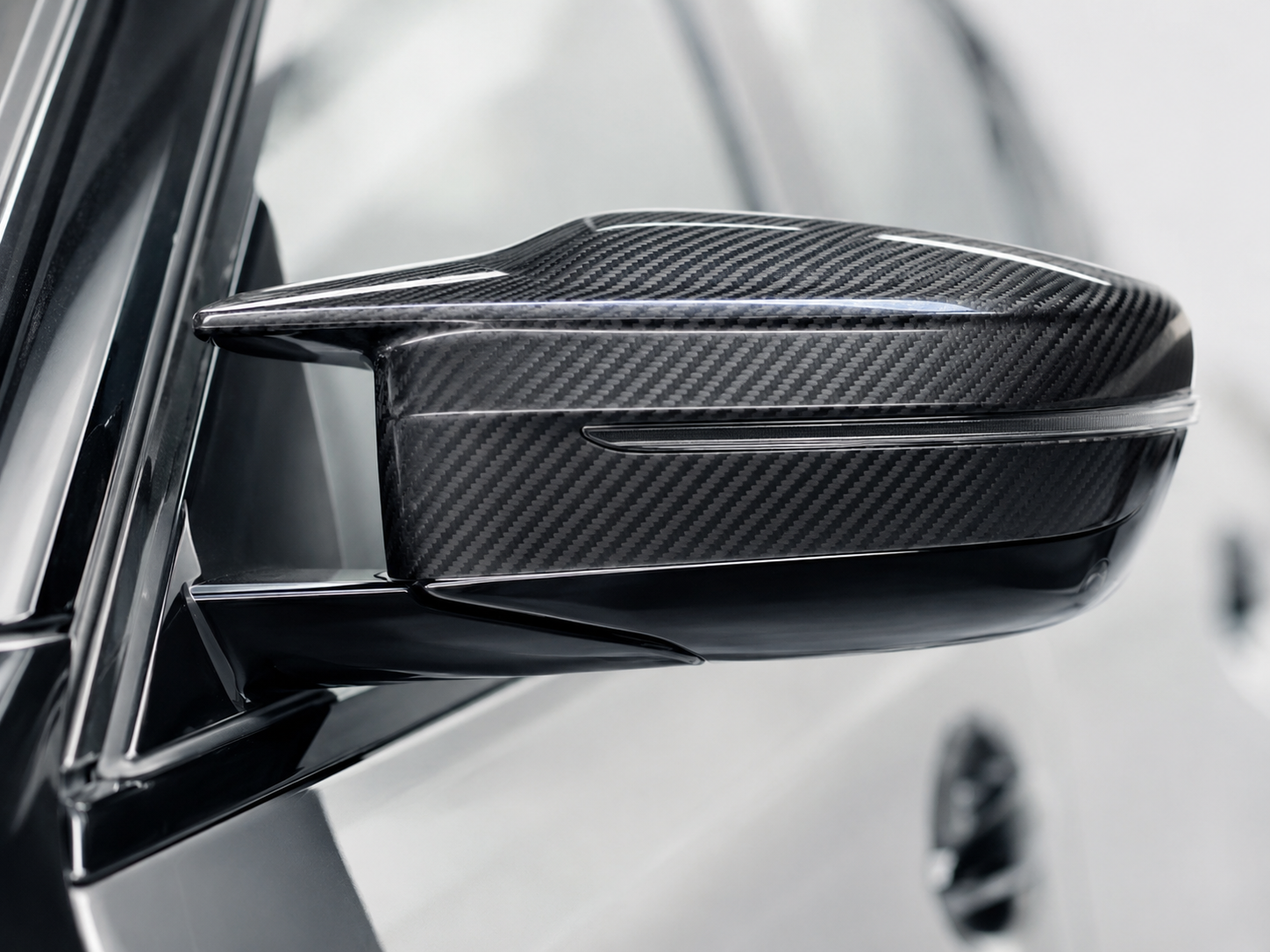
a customer-approved Master Sample or Approved Sample;
SAMPLEthe drawing and finish specification;
DRAWINGA/B/C visible-zone definitions, where A means directly visible, B indirectly visible and C non-visible;
ZONESproject-defined gloss or color readings when the customer specifies them;
READINGSa defect-location record and photographs when required.
RECORDNEXWAVE does not treat an undefined “Class A” label as a complete standard. The visible face, viewing condition, weave direction, coating, allowable repair and approval source still have to be stated.
Protect the accepted condition
Inspection starts after release from the tool, not only after paint. That allows weave distortion, resin-rich or resin-lean areas, pinholes and handling damage to be addressed before later finishing hides or increases the problem. Repair, refinishing, concession or scrap follows the approved surface requirement and formal authority for that project.
After acceptance, protection may use
surface film, nonwoven or foam separators, individual bags or cartons,
edge guards, restraints, orientation or moisture labels and a packing check.
The exact combination follows the part's visible zones, protruding features, destination and handling risk.
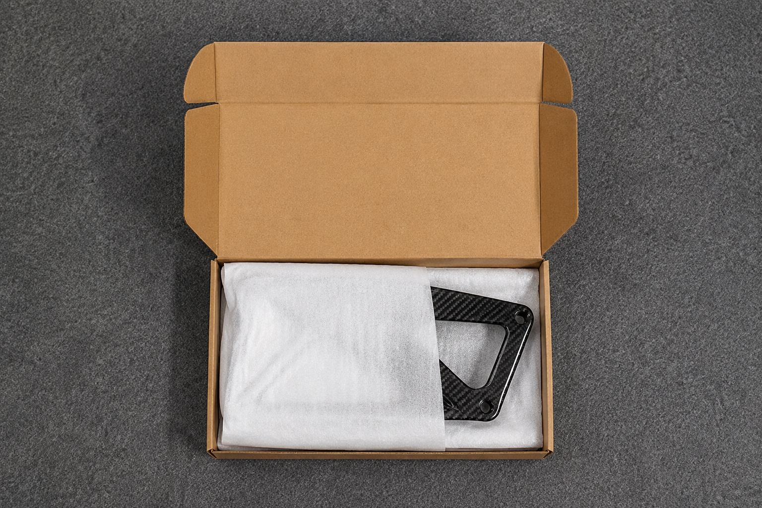
The buyer receives the visible part in the agreed appearance and protected delivery state, instead of paying to sort, refinish or replace an avoidably damaged batch after arrival.
Turn the Approved Sample into the Result the Next Order Must Match
A successful first article is not a repeat-production system by itself. The next batch can change if the material source, layup instruction, tool condition, CNC program, surface reference or packing method changes without an affected-scope review.
Build one approved production reference
The repeat-order baseline can include:
approved sample or first-article state;
released drawing and revision;
material system and applicable batch or source requirements;
laminate, charge or process instruction;
tool and fixture identity and condition;
CNC program and revision;
inspection method, sample plan and retained record;
approved surface and delivered state;
packing, labels and shipment documents.
Do not hide a change inside a repeat order
A change to the released drawing, material, laminate, tool, fixture, program, process, acceptance method, surface, packing or document requirement is reviewed for its affected scope. The result may be continuation, reinspection, a new first article, revalidation or customer reapproval, depending on what changed and which requirement it can affect.
This gives the buyer a practical answer to “Will the next batch match what I approved?” The answer is based on a controlled production reference and a visible change decision, not factory memory or visual similarity.
Define the Complete Delivered Part, Not Just the Molded Shape
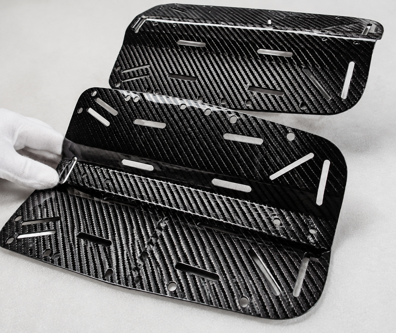
Two suppliers can quote the same carbon fiber shape and still be pricing different deliveries. One may stop at the molded blank. Another may include trimmed edges, drilled holes, inserts, coating, assembly checks and export packing.
Define the required state as an operation and responsibility map:
| Delivery element | Decision to make | Customer result |
|---|---|---|
| Formed part | Material, laminate, forming route and tool responsibility | The approved molded construction and surface state |
| Functional features | Trimming, holes, countersinks, inserts, bonds and edge treatment | A part ready for its stated interface rather than unresolved secondary work |
| Finished surface | Sanding, polishing, clear coat, paint, visible zones and protection | The agreed appearance when the part is presented and delivered |
| Assembly | NEXWAVE-supplied, customer-supplied and third-party items; fit and inspection responsibility | A defined component or assembly rather than a collection of assumed operations |
| Quality evidence | Characteristics, methods, sampling, records and approval source | The evidence needed to accept the delivered condition |
| Packing and documents | Protection, labels, CoA, applicable TDS/SDS and selected project reports | A complete order that can be received without discovering a missing responsibility |
NEXWAVE can combine in-house material preparation, forming, CNC, inserts/bonding, surface work, assembly, inspection and packing when they fit the confirmed route. Any external or customer-controlled operation remains visible in the quotation and quality plan.
The goal is not to make every operation part of every order. It is to make sure the buyer and supplier are building the same finished thing.
Check the Factory Evidence Behind the Proposed Solution
Supplier qualification should test the route proposed for your part. A long equipment list is useful only when the people, tools, process controls and inspection resources can be connected to the job that has to be done.
ROUTE-RELEVANT NEXWAVE RESOURCES
| Evidence layer | Current resource | What it can support, with project review |
|---|---|---|
| Engineering | 30+ composite-material design engineers and 6 process engineers within a team of 100+ employees | DFM, material/laminate direction, tooling, process planning and assigned engineering support |
| Material preparation | Three prepreg production lines, cold-storage capability, two Zünd cutters, ten layup stations and ten Busch vacuum pumps | Controlled material preparation, cutting, layup and vacuum work for applicable routes |
| Forming | Five autoclaves, five 2500-ton-class hot presses, two forged-carbon presses, two filament-winding machines and one tube-rolling line | Multiple forming families selected by geometry, material, tooling, surface and stage |
| Secondary operations | Four five-axis CNC machining centers plus recorded bonding, finishing and assembly resources | Trim, holes, interfaces, finished surfaces and agreed component delivery |
| Quality | An eight-person Quality team, two C-scan systems, ZEISS ACCURA CMM and recorded test resources | Project-selected dimensional, internal-condition, surface, material and release evidence |
| Facility | An 80-mu site, approximately 53,333 m², with about 30,000 m² of buildings, 26,000 m² of production area and a 10,000 m² assembly workshop | Space for the connected manufacturing and assembly scope, subject to actual project loading and route review |
These facts establish available resources. They do not by themselves promise a tolerance, cycle time, monthly capacity, defect rate or result. The proof that matters is the subset attached to your proposed route: the responsible engineers, applicable machine and tool, controlled process output, inspection method and approved release evidence.
Agree What Passes Before the Order Reaches Release
“Inspected” is not an acceptance criterion. A drawing dimension, approved sample, C-scan indication, fit check and packaging requirement each need a defined source, part condition, method and approval responsibility.
FOR EVERY CRITICAL REQUIREMENT, AGREE
what source controls it, such as the released drawing, Approved Sample, specification or quality plan;
SOURCEwhat feature or condition is checked and at which production state;
STATEwhat method and sampling plan apply;
METHODwhat record is retained or supplied;
RECORDwho can approve the result or any departure.
AUTHORITYWhen a requirement is missed
The buyer-visible sequence is:
detect → identify and isolate → confirm affected scope → NCR/MRB review → select the authorized disposition → obtain customer approval when required → correct, reinspect or revalidate as applicable → authorize release → update the repeat baseline only when approved
Rework back to the released requirement may be internally authorized under the applicable Quality responsibility. Repair or use-as-is/concession requires customer written approval when it changes or accepts a departure from the released requirement. Scrap is recorded and excluded from release.
Which records travel with the order
NEXWAVE retains the applicable manufacturing and Quality records. Batch CoA is supplied with each batch, and TDS/SDS is supplied on first delivery or after a document revision. Full FAI/CMM reports, C-scan reports, NCR/CAR records and photographs or video are supplied when the quotation, quality plan, NDT requirement or actual deviation route calls for them.
This keeps the shipment evidence relevant to the project while preserving traceability for later review. It also prevents an unapproved departure from becoming the part the customer receives or the baseline the next order repeats.
Continue with the Specialist Review That Matches the Problem
Choose the review that owns the remaining technical question. The controls remain visible while their target pages are being released.
Engineering & Development
Design, DFM & Reverse Engineering
Geometry, missing definition, sample-to-CAD work or manufacturability remains open
Layup Design
Ply architecture, reinforcement orientation or laminate detail remains open
Tooling & Mold
Tool split, release, mold, trim/drill, assembly or inspection fixture remains open
Forming & Processing
Autoclave Curing
Prepreg/autoclave route fit, working envelope or execution conditions remain open
Compression Molding
Matched-tool compression route fit and execution remain open
Molding & Processing
The broader forming/process family has not yet been resolved
Filament Winding, Roll Wrapping & Pultrusion Boundary
A tubular/continuous-fiber route or the external pultrusion responsibility boundary remains open
RTM & Infusion
Dry-reinforcement, resin-flow, tooling and route-fit questions remain open
Secondary Operations
Carbon Fiber CNC Machining
Trim, hole, edge, datum, fixture or machined-feature depth remains open
Bonding, Inserts & Assembly
Insert, bonded interface, supplied item, assembly or fit-check depth remains open
Appearance & Surface Finishing
Visible surface, finishing, coating, inspection or protection depth remains open
Control & Execution
Production Process & Material Control
Material state, route execution, process record or traceability depth remains open
Quality Control & Inspection
Inspection, acceptance evidence, release or formal-deviation depth remains open
Prototype to Mass Production
Sample, pilot, ramp, capacity or production-transfer questions remain open
If the unresolved question is primarily about material selection, industry or compliance conditions, or a finished custom component rather than a manufacturing method, continue to the relevant Materials, Industries or Custom Parts review. When a manufacturing method or responsibility boundary remains open, use the appropriate specialist review above.
Frequently Asked Questions
Yes. Those inputs can start a definition review. NEXWAVE will identify what can be inferred, what must be measured or rebuilt and which load, interface, surface or approval questions still block the manufacturing route. A sample or photo does not automatically create production-ready CAD.
No. Route fit depends on geometry, material form, tool concept, visible surfaces, quantity stage, downstream features and validation. The equipment proves that a process family is available; DFM confirms whether it fits the part.
No. C-scan can support applicable delamination and porosity evaluation, but coverage and sensitivity depend on geometry, thickness, material attenuation, coupling and defect orientation. The quality plan should define coverage, acceptance and any alternative method.
No. Batch CoA is standard, and TDS/SDS accompanies first delivery or a document revision. Full FAI/CMM, C-scan, NCR/CAR and visual records are supplied when selected by the quotation, quality plan, NDT requirement or actual deviation route.
The released drawing, material and laminate/process definition, tool and fixture, CNC program, inspection basis, approved surface, delivered state and packing/document requirements form the project reference. Changes are reviewed for affected scope and may require reinspection, revalidation or reapproval.
No. RTM and liquid-infusion routes are currently available for applicable projects. In-house pultrusion is not currently supported, so a pultruded-profile requirement needs an external sourcing/responsibility review or another route assessment.
Start with What You Already Know About the Part
Send the current drawing, CAD model, sample information or developing requirement. Add what the part must do, where it will work, how it connects, the planned quantity or stage and what must be true for acceptance.
NEXWAVE will use that information to identify the blocking questions and the right manufacturing or specialist review. Files continue through the approved reply-email route after the written website request.