Control the Carbon Fiber Manufacturing Process From First Part to Repeat Order
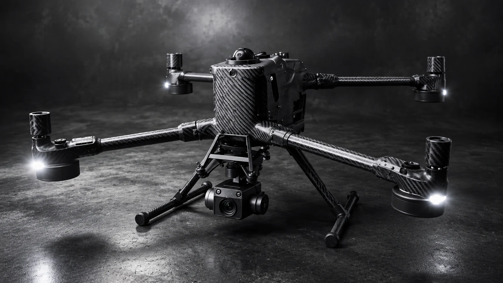
NEXWAVE connects route selection, material and process control, inspection and released baselines so finished CFRP parts can be manufactured against one approved definition.
A Finished Part Needs
More Than a Process List
Producing one acceptable sample is not the same as controlling the next order. A repeatable carbon fiber manufacturing process keeps the same approved part definition connected to the material, tool, forming route, post-cure operations, inspection basis and release status.
That connection gives engineering and sourcing teams four practical outcomes:
 FIG 01-A · ROUTE RISK REVIEW
See route risk before tooling and samples. Geometry, material form, visible surfaces, interfaces, quantity and verification needs are reviewed before an unsuitable route absorbs more project time and tooling cost.
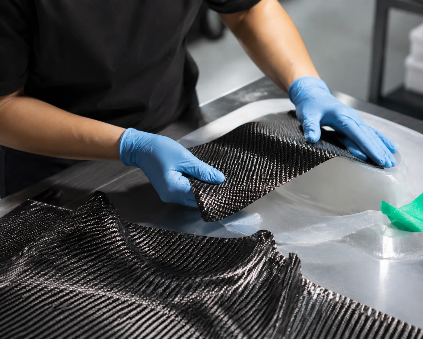 FIG 01-B · PRE-CURE CHECK WINDOW
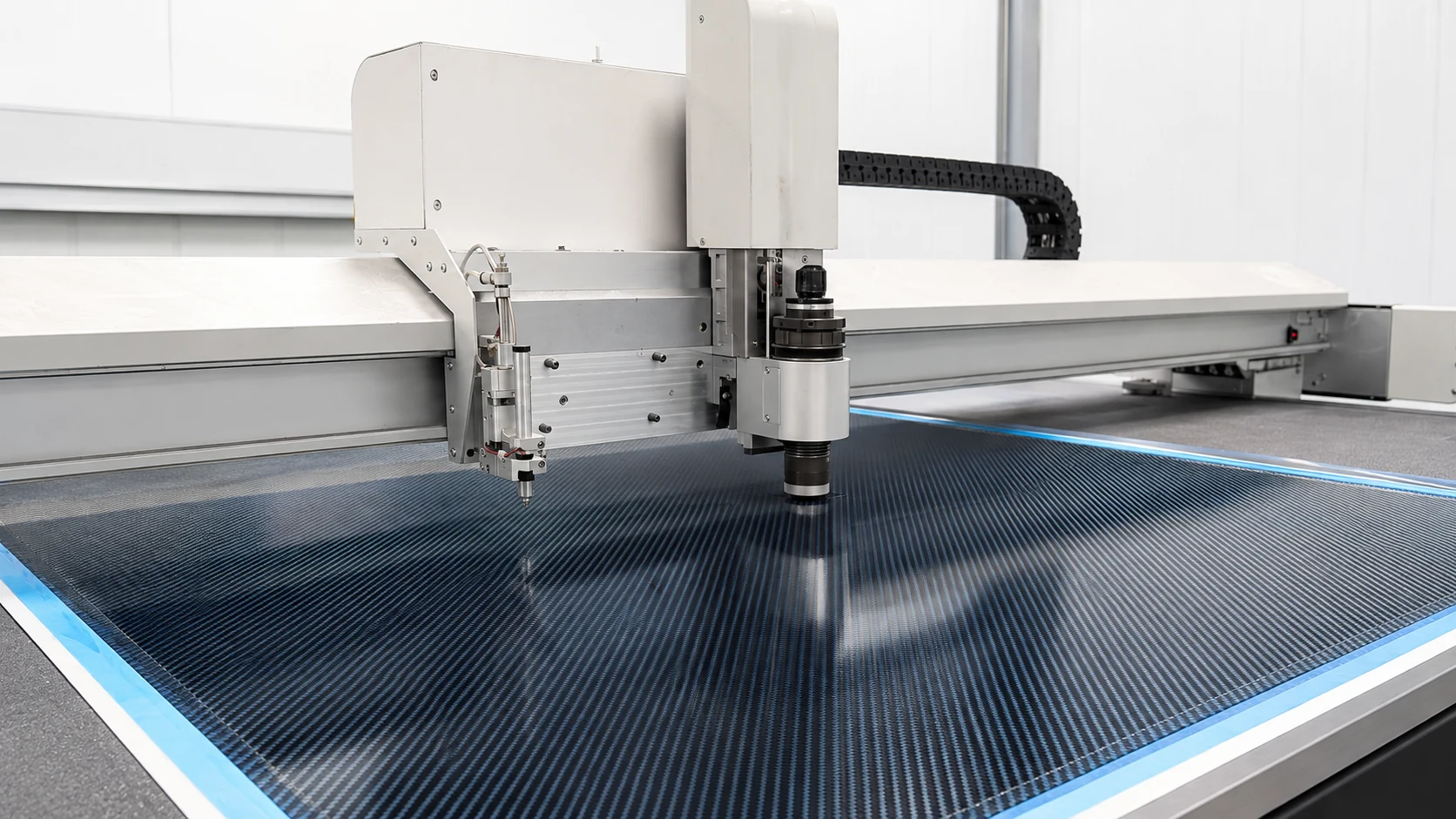
Catch correctable errors before irreversible processing. Material, cut data, layup, inserts, vacuum preparation and release status can be checked while correction is still possible—not after a wrong condition has been cured into the part.
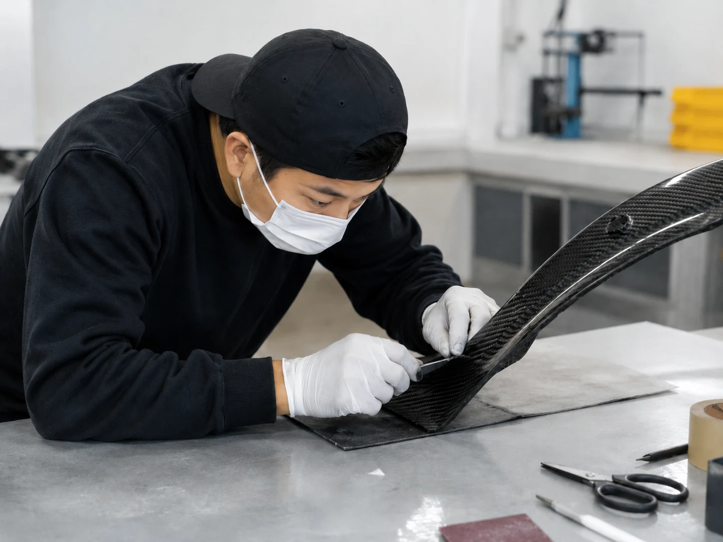 FIG 01-C · FIT, FINISH & CTQ CARRY-THROUGH
Protect fit, finish and CTQs through downstream work. CNC machining, bonding, assembly, surface finishing and inspection continue to use the same drawing, datum, interface and acceptance basis.
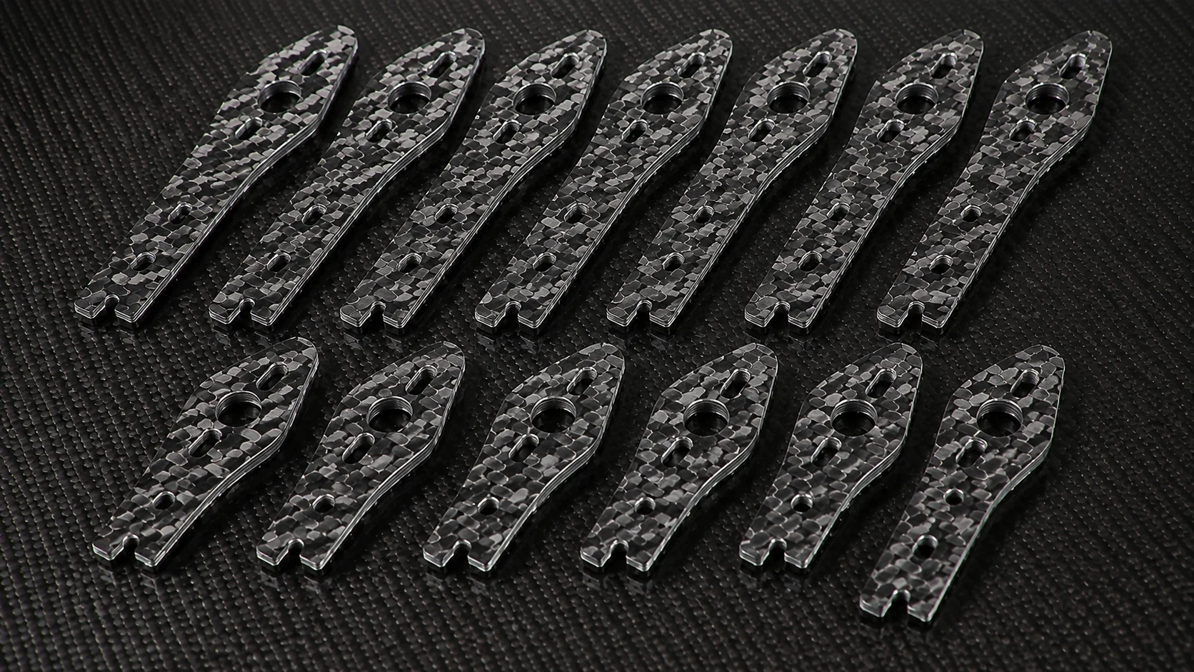 FIG 01-D · RELEASED BASELINE FOR REPEAT ORDERS
Limit disruption and protect later orders. Connected records help define affected product when something departs from requirements, while only an authorized released result can become the baseline for repeat production.
The scope is downstream finished-part manufacturing
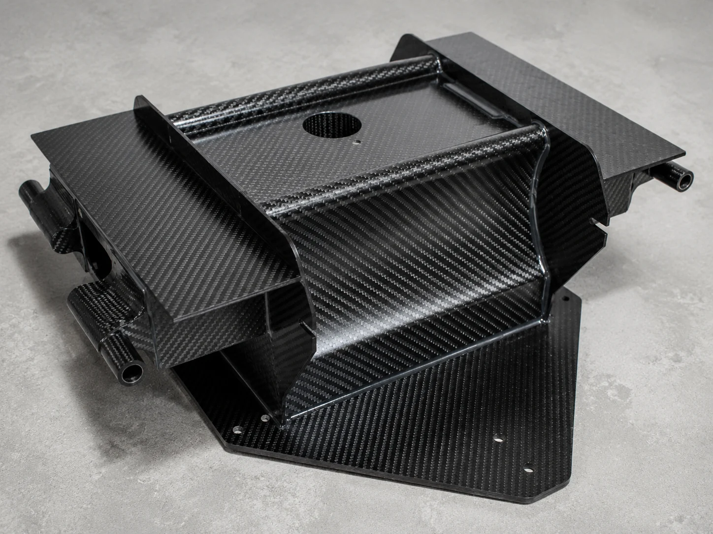
Within the carbon fiber value chain, NEXWAVE’s role is focused on finished-part manufacturing rather than upstream precursor or carbon-fiber production. The page begins where an approved or proposed fiber/resin system, prepreg or other reinforcement form becomes an input to a CFRP part route. It then follows the decisions that change the delivered component: tooling, cutting and layup, forming or cure, demolding, machining, bonding, assembly, finishing, inspection, release and repeat-order control.
| A sample can show | A controlled production answer must also show |
|---|---|
| The part can be molded once | Which material, tool, program and work definition produced it |
| The visible face looks acceptable | Which surface definition, process and inspection basis accepted it |
| Holes and interfaces fit one assembly | Which datums, machining program, fixture and fit check protect the interface |
| One result passed inspection | Which released state later orders must repeat and which changes trigger review |
Your question is therefore not simply, “Do you have an autoclave or press?” It is, “Can you explain which process fits this part, what must be controlled, what evidence establishes acceptance and what the next order will repeat?”
Let the Part Requirements
Choose the Manufacturing Route
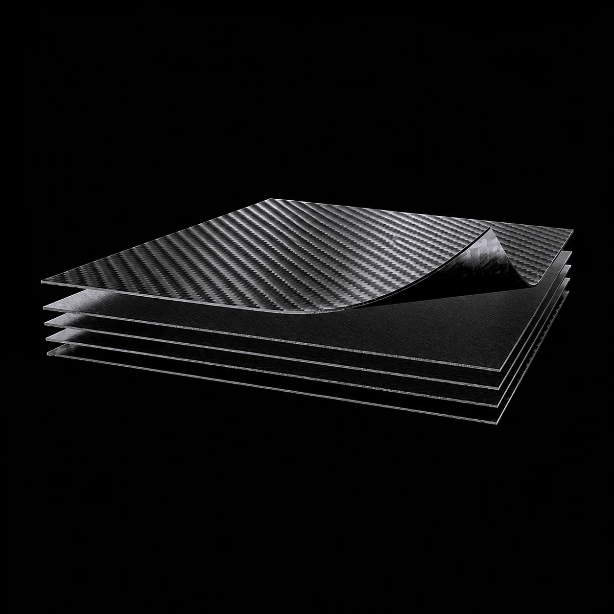
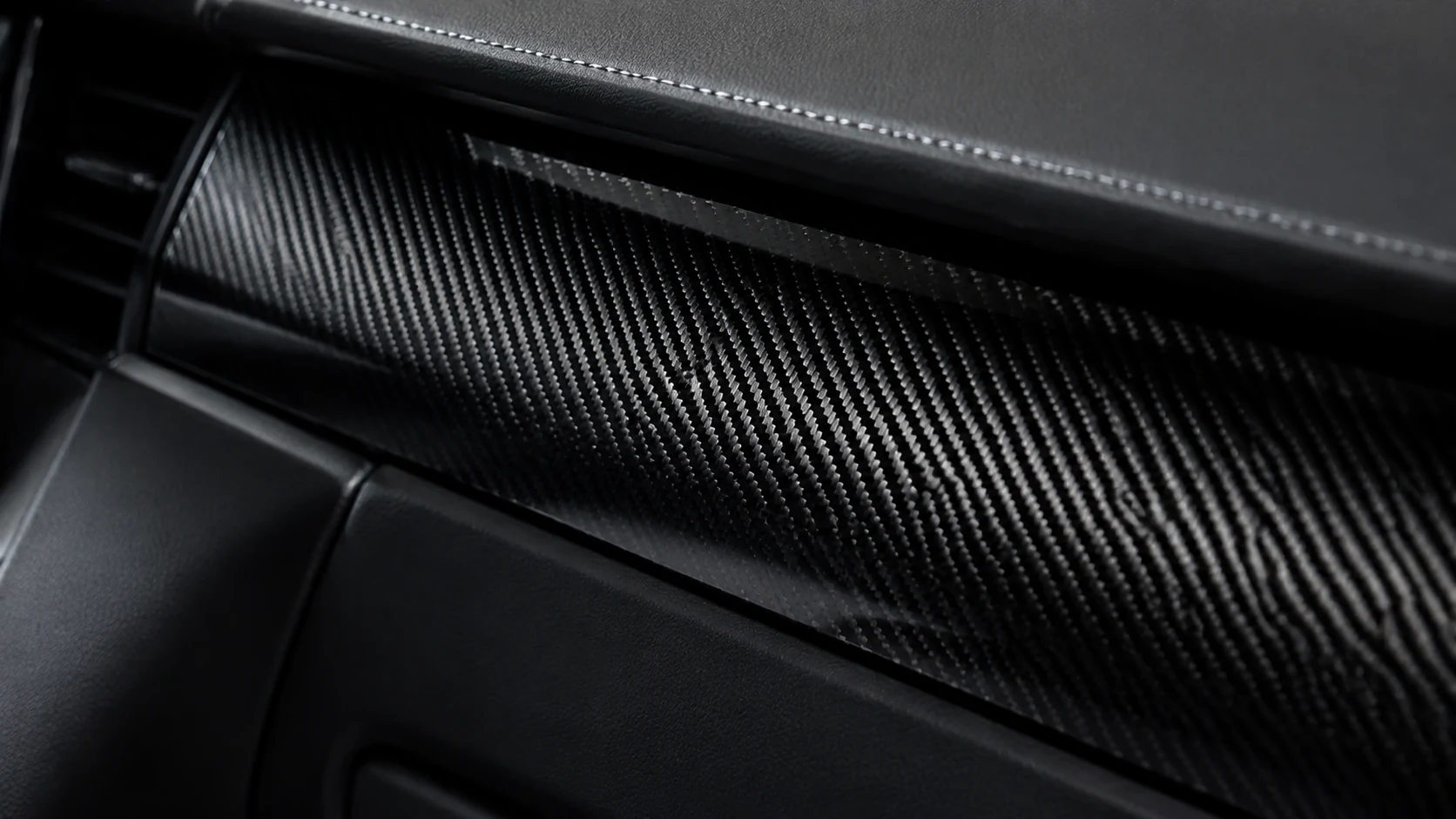
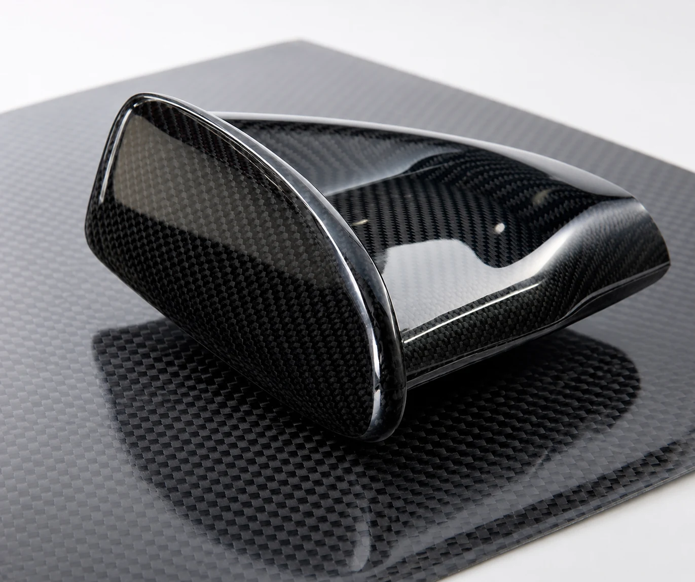
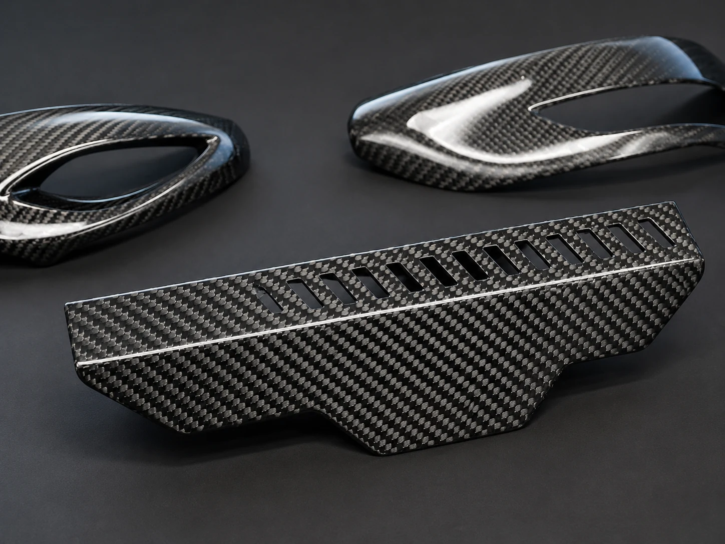
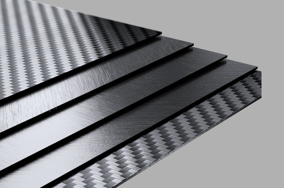
FIG 02 · MATERIAL FORM / LAMINATE BASIS
The same CAD model can produce very different quotations because suppliers may be pricing different assumptions. Depth, curvature, draft, demolding access, laminate form, visible-surface expectations, metal interfaces, order quantity, tool life and validation scope can change both the route and what the route must prove.
REGISTER 02-A · FIVE CONDITIONS RESOLVE TO ONE ROUTE ENTRY
| Part or program condition | Route effect to review | What the buyer should expect to see |
|---|---|---|
| Deep draw, tight curvature or difficult demolding | Tool access, split strategy, charge or ply placement and release approach may change | A route rationale tied to geometry, not a generic process ranking |
| Structural load path and laminate form | Material form, fiber-direction continuity, consolidation route and validation plan may change | An identified material/laminate basis and ownership boundary |
| High-visibility A-side surface | Tool surface, material placement, finish route and visual acceptance become route inputs | A visible-surface definition and planned verification point |
| Inserts, bonded interfaces or tight hole patterns | Pre-positioning, post-cure machining, datum transfer and fit checks may change | An interface strategy connected to the drawing and assembly |
| Prototype, validation run or repeat quantity | Tool construction, cycle strategy, work content and evidence package may change | A quantity-specific route and cost-driver explanation |
A real route decision: hollow structural arm
In an anonymous 2025 industrial robot-arm project, NEXWAVE compared autoclave, compression-molding and secondary-machining implications for a hollow, non-constant-section CFRP arm. The review considered demolding and core strategy, repeat volume, a visible outer surface, metal interfaces, tooling and validation. The selected route used compression molding with prepreg placement and pre-positioned metal inserts, followed by tooling, a first article, a 50-piece validation run and production release.
The value of the example is not that compression molding is always preferable. It shows that the selected process followed the part and program conditions. You can use the same logic to challenge a quotation: Which requirement eliminated the other routes? Which assumptions remain open? Which cost comes from the part, and which comes from a supplier’s preferred equipment?
Resolve Manufacturability Conflicts
Before Tooling and Samples
A manufacturing review should replace a vague “yes, we can make it” with decisions the customer can approve. NEXWAVE checks whether the proposed route can reach the required surfaces and radii, release from the tool, maintain thickness changes, carry datums into machining, accommodate inserts or bonded interfaces and leave the necessary inspection access.
| Feature under review | Manufacturing risk | Possible response | Decision evidence |
|---|---|---|---|
| Tight radius or abrupt section change | Bridging, wrinkle, resin-rich area or difficult material placement | Revise the feature, change the layup/tool approach or validate the area | Marked CAD/drawing, risk note and validation point |
| Negative draft or restricted release | Tool lock, part damage or uncontrolled split line | Change draft, define a split tool or revise the release strategy | Tool/release review and customer decision |
| Hole near an edge or thick transition | Edge damage, datum loss or machining access problem | Move the feature, add local definition or change machining/fixture strategy | Machining and inspection plan |
| Undefined mating interface | A good standalone part may still fail assembly | Confirm datums, mating conditions, hardware and fit method | Interface drawing and fit-verification basis |
| Visible and non-visible surfaces not separated | Unclear tool finish, texture, repair and acceptance scope | Define A-side/B-side zones and approved surface basis | Surface map, sample or project criterion |
NEXWAVE may propose fiber-direction, material/resin-system and laminate-schedule directions within the assigned review scope. Screening may include engineering judgement and classical laminate theory. FEA and final structural approval normally remain with the customer, its designated third party or another agreed qualified party.
What a useful review returns
A practical output may include a marked drawing or CAD view, revised geometry, route direction, tooling and release notes, missing interface or acceptance questions, a risk list and a validation plan.
The customer retains the decision on product requirements and structural approval; NEXWAVE turns those requirements into a manufacturable route and identifies what still needs confirmation.
In one anonymous UAV-frame review, early inputs included an exterior model, photographs and a finished-part target below 350 g, but not a closed laminate, tolerance, interface or inspection definition. The review identified tight bends, radii below 3 mm, undefined datums and negative draft. After customer-approved changes, the finished part was recorded at 335 g, the four motor-hole deviations were within ±0.1 mm, CMM results conformed to the drawing, the Class-B visual result was accepted and the first article passed customer acceptance. The six-week project result belongs to that project; it is not a universal schedule promise.
Stop Correctable Errors
Before Cure
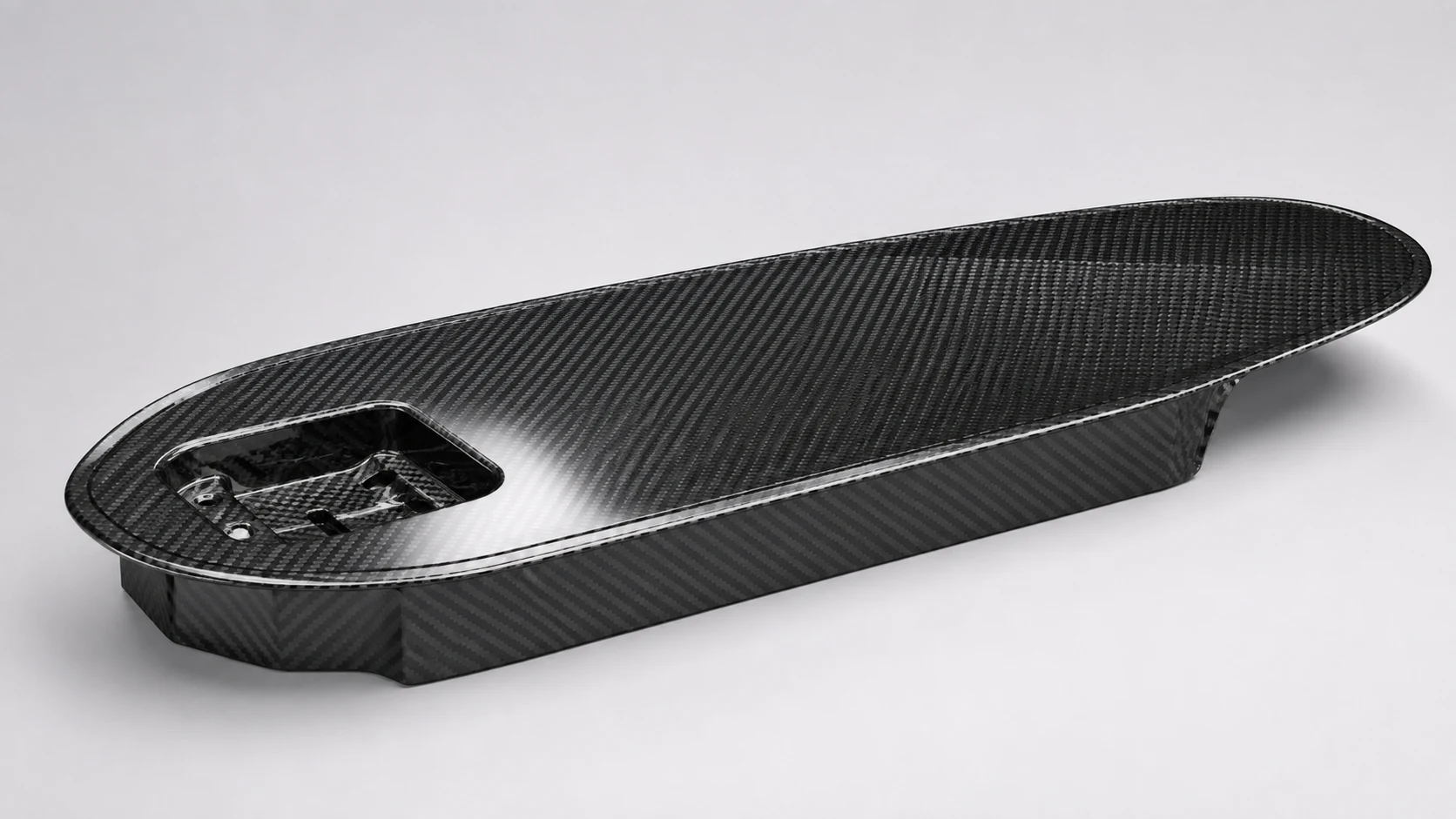
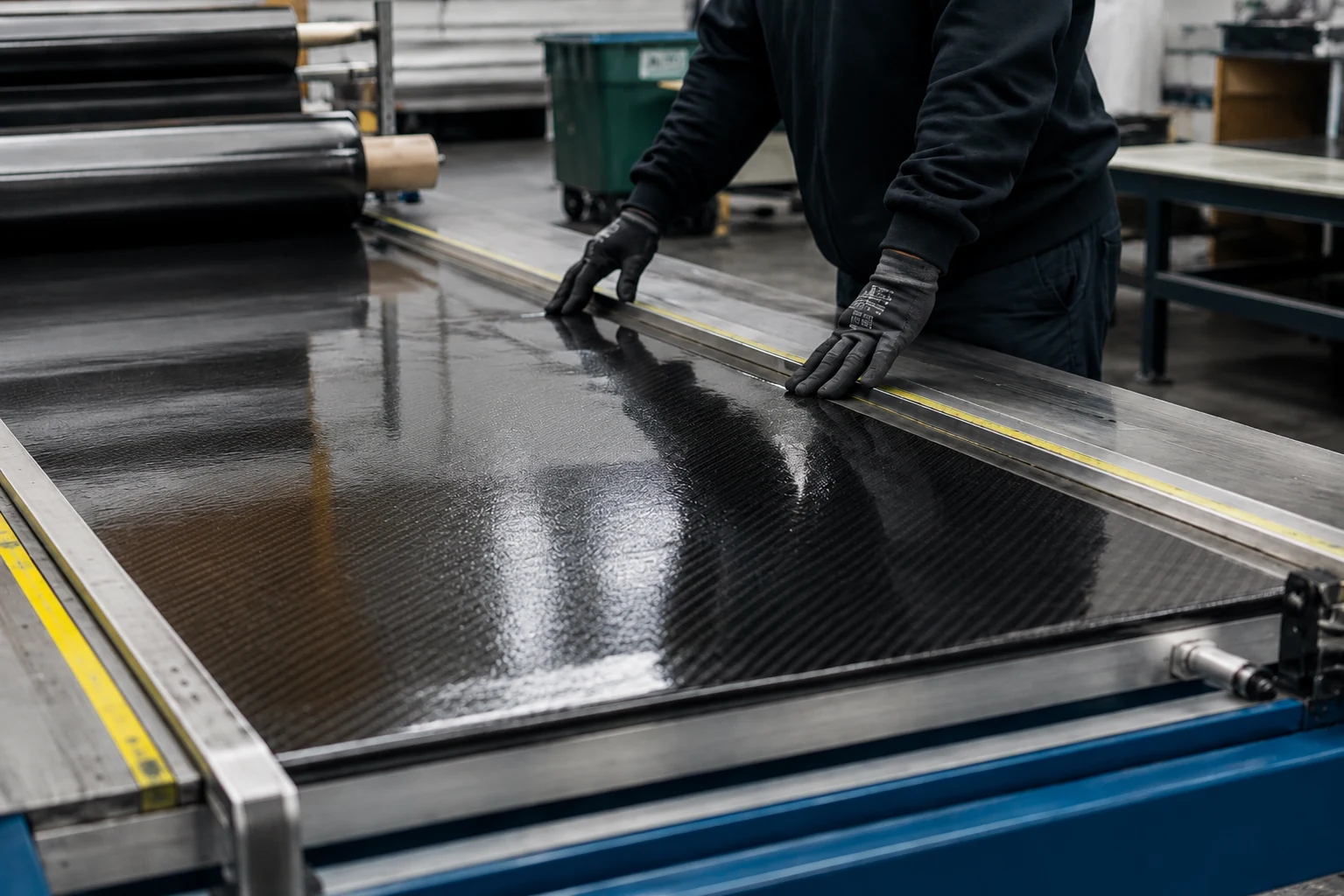
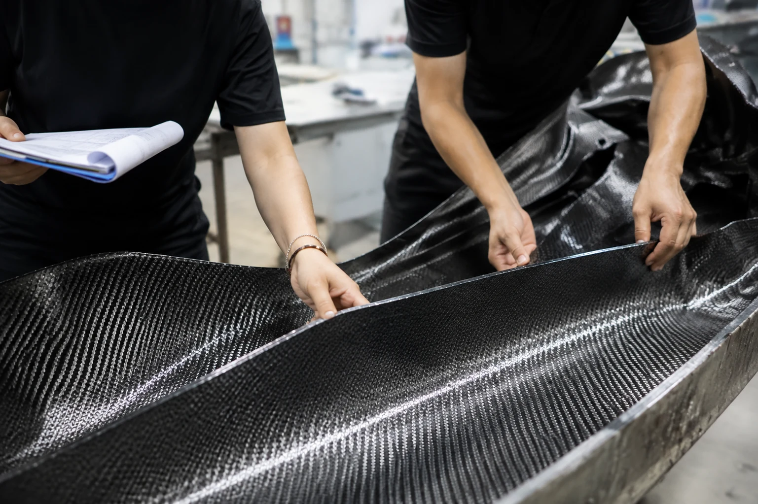
Many laminate errors are inexpensive to correct only while the material remains uncured. Once a wrong material, cut-kit version, ply orientation, insert, core detail or vacuum condition enters forming or cure, you may face a remade sample, part sorting, repair or scrap instead of a controlled correction.
NEXWAVE connects material issue, tool and cut-data revision, layup status, vacuum preparation and pre-cure release in a job-specific stop gate. The exact checks follow the material, route and project quality plan; this is not one universal checklist for every CFRP part.
| Pre-cure control point | What is checked | Finished-part or order risk if missed |
|---|---|---|
| Material identity and status | Approved grade/form/resin system, batch, condition and permitted alternative | Wrong laminate input, uncontrolled substitution or batch investigation |
| Tool and cut-data revision | Tool status, cut file, ply/charge definition and current drawing | Geometry, datum, ply-shape or local-thickness mismatch |
| Layup and local features | Ply sequence/orientation, reinforcement, core and insert placement | Wrong stiffness path, local thickness, interface or internal condition |
| Vacuum or pre-forming preparation | Bagging/connection state or applicable charge/preform readiness | Consolidation, surface, thickness or process-window exposure |
| Hold and release status | Required checks complete and open mismatch resolved | Irreversible processing of an unapproved job state |
NOTE — The first occurrence of a layup traveler on this page means the project’s production routing record: it connects the job, material and part definition to the work completed and the applicable sign-offs.
A ply error caught before it became a cured-part problem
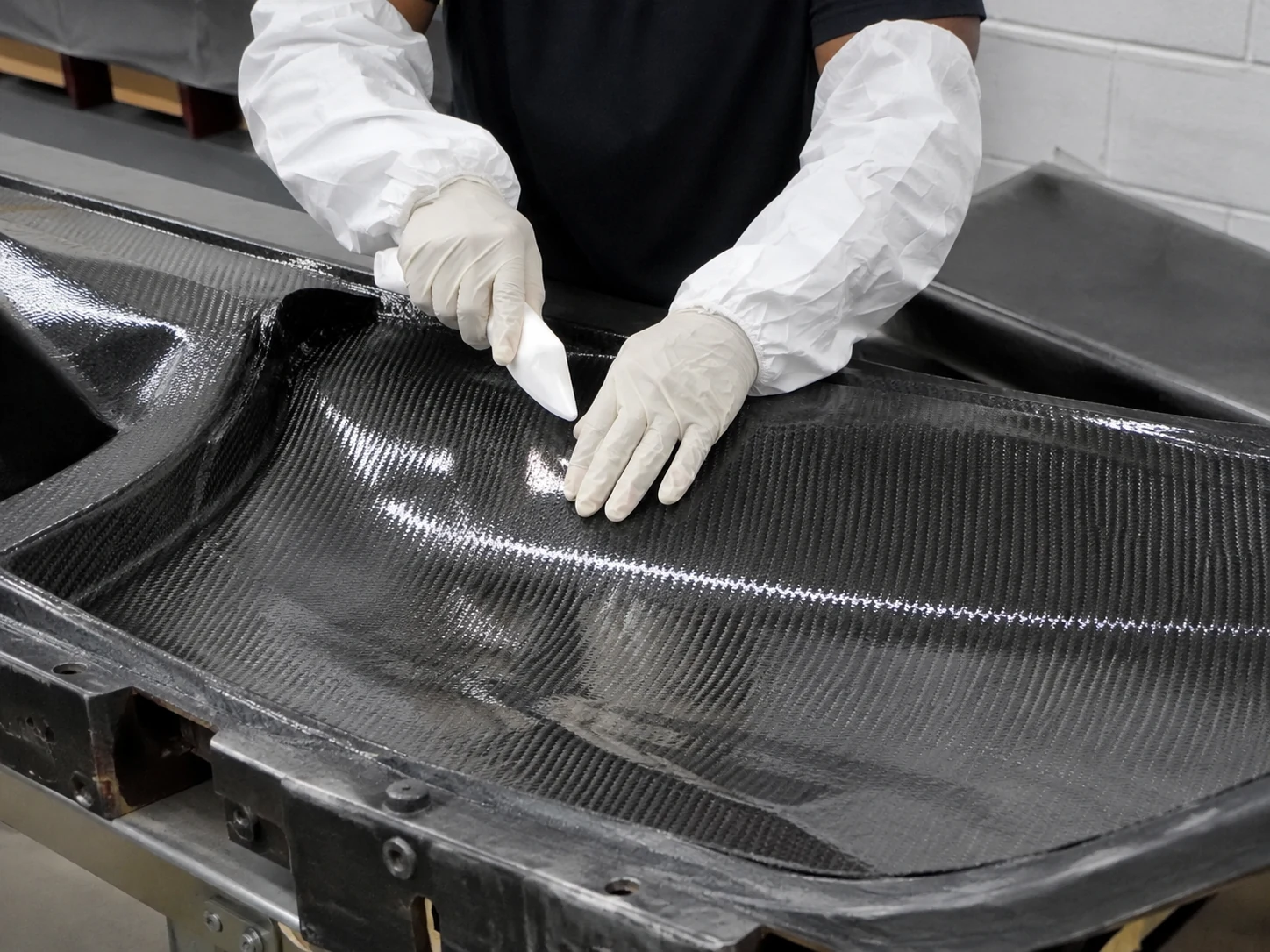
In an anonymous February 2026 UAV centre-wing-box layup, ply 10 was +45° and ply 11 should have been −45°. During rapid consecutive layup, the same orientation was selected for ply 11. The error was detected immediately after that ply was placed and before ply 12 or any later ply was added. Because the laminate was still uncured and the affected ply was exposed, the team removed and replaced ply 11 without disturbing the lower plies.
The project retained operator checks on each ply and in-process Quality verification. It also added a mandatory stop after every four plies for three-point cumulative-thickness measurement and a sequence/symmetry review, with reinforced Quality coverage on the first five plies. This additional check did not replace the layer-level controls; it addressed cumulative sequence errors that a dense series of visual checks could miss.
Control the Part and Tool Response,
Not Only the Machine Setpoint
A normal chamber reading does not automatically prove that the tool and laminate followed the approved process window. Material response, tool mass, load arrangement, thermal lag, pressure, vacuum and time can affect the actual part state. NEXWAVE therefore connects the approved program to applicable part/tool measurements, the run record and an escalation rule.
| Route family | Approved basis | Monitored state may include | Departure question |
|---|---|---|---|
| Autoclave curing | Material TDS, bagged part/tool configuration, program and validation basis | Part/tool/chamber temperature, pressure, vacuum, time, alarms and run status | Did the part/tool response remain within the approved basis? |
| Hot pressing or compression molding | Material/charge, tool, closure or consolidation basis and program | Pressure, temperature, time, tool/machine state and charge response | Does the run still match the approved material, tool and program? |
| Forged-carbon molding | Compound/material system, charge placement, tool and molding basis | Charge, pressure, temperature, time and resulting run state | Did material, charge or monitored conditions leave the reviewed route? |
NEXWAVE operates five autoclaves and five hot presses, but equipment availability does not establish part fit. Current autoclave chamber sizes range from approximately Ø1.2 m × 2.0 m to Ø3.2 m × 6.0 m, and the hot-press fleet comprises two 200-ton, two 500-ton and one 1,000-ton press. Actual part, tool and load fit—and the required unit pressure—remain engineering-review decisions.
DEVIATION RECORDFORMAL ROUTE
A documented temperature-response departure
In an anonymous November 2025 autoclave load, four curved laminate parts measuring 1,200 × 800 mm showed a part/tool temperature-response departure. The load entered a pending-review state. A process engineer proposed a temporary 125°C intermediate hold using the material TDS allowance for time adjustment within a 120–145°C equivalent-cure range. The change was documented through the formal deviation route and signed by Process and Quality.
The production manager authorized continued processing only; that decision did not release the product. Final release remained with the Quality manager and followed dimensional review, water-immersion ultrasonic C-scan and differential scanning calorimetry (DSC) evidence.
The C-scan recorded a 1.2% indication area over the full projected inspection area against this project’s single-indication limit of no more than 2.0% under the applicable internal NDT standard. The value describes gate-threshold ultrasonic indication area, not microscopic void content. Four independent traveller panels, positioned at the four tool-flange locations and not cut from the finished parts, recorded DSC cure results of 92.3%, 92.1%, 93.0% and 92.6% against the submitted project basis of at least 90%.
The quality agreement allowed internal deviation disposition when the finished parts met the drawing and mechanical-performance basis. The deviation record was included in the batch data pack for customer review. Quality authorized release on 25 November 2025.
Carry the Approved Definition Through
Machining, Bonding and Finishing
A conforming molded part can still become unusable after cure. CNC trimming, drilling and countersinking can damage edges or shift features. Insert installation and bonding can change interface location or bond-line condition. Assembly can reveal stack-up problems. Sanding, clear coating or painting can damage the weave or miss the approved visible-surface state.
NEXWAVE keeps the drawing revision, datums, interface definition, machining program and fixture, surface map and staged verification connected to the same part definition.
CNC Machining
Program / fixture revision locked to drawing datums
Insert & Bonding
Interface drawing · material compatibility
Assembly & Fit
Hardware · mating conditions · fit verification
Surface Finishing
Surface map · approved sample criterion
| Operation | CFRP-specific risk | Control linked to the approved part | Verification point |
|---|---|---|---|
| CNC trimming, drilling and countersinking | Delamination, edge damage, hole-position error or datum loss | Program/fixture revision, clamping and protected geometry | Hole, edge and dimensional check |
| Insert installation and structural bonding | Wrong location, preparation, adhesive system or bond-line state | Interface drawing, material compatibility and controlled work definition | Position, fit and applicable bond/process confirmation |
| Assembly and fit | Orientation, stack-up or mating-interface mismatch | Assembly revision, hardware and mating conditions | Agreed fit or assembly verification |
| Edge sealing, sanding, polishing, clear coating or painting | Exposed fibers, weave damage, pinholes, gloss/color mismatch or protected-surface loss | Visible/non-visible surface map, finish system and approved sample or criterion | Visual and applicable surface, color or gloss check |
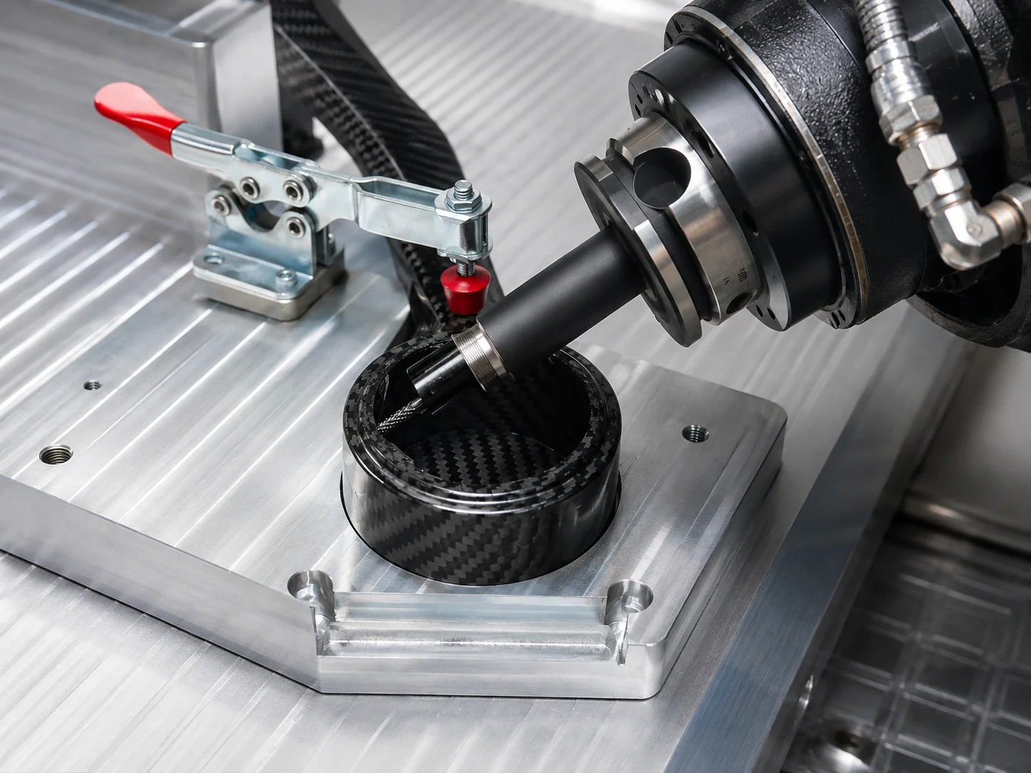
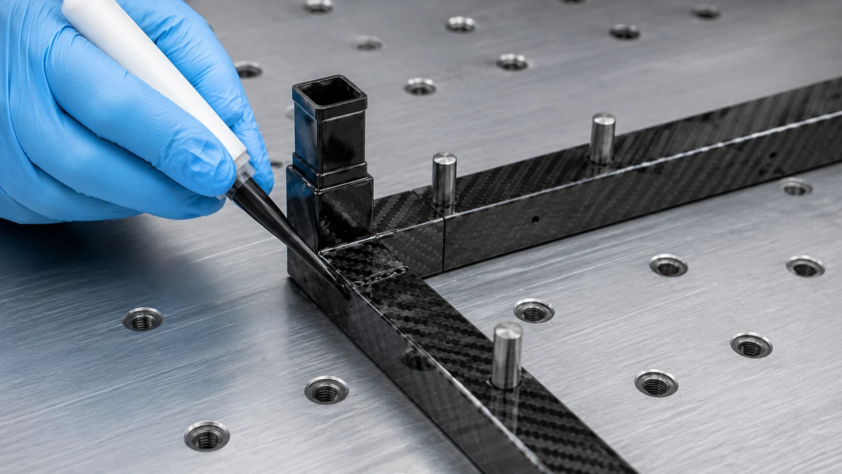
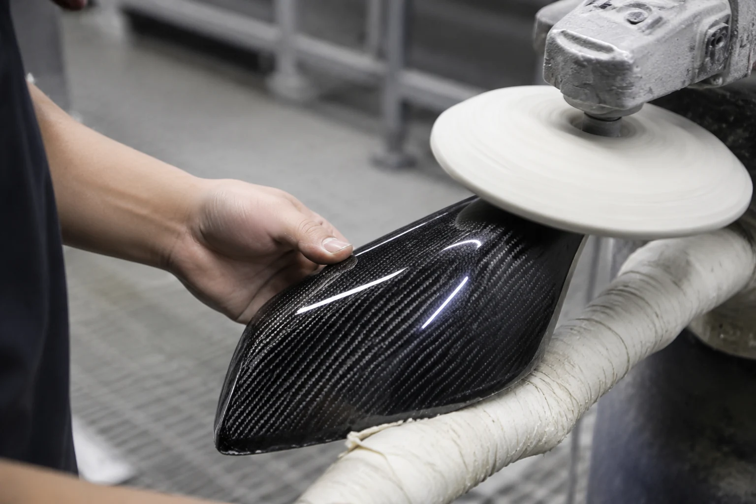
NEXWAVE’s in-house downstream scope includes five-axis CNC machining, insert installation, structural bonding, assembly, edge sealing and surface-finishing operations. The included operations and acceptance evidence are confirmed per project; listing a capability does not imply that every part receives every operation.
In an anonymous 2026 UAV structural-part program manufactured from customer-supplied laminate and material specifications, NEXWAVE carried 50 first-batch parts through autoclave processing, machining and project-selected verification. FAI/CMM recorded dimensional acceptance, the agreed C-scan result was within its project criterion, and all 50 parts completed the specified mating check without interference. Two specimens were destructively tested by the customer and exceeded the project’s stated tensile design value. These results belong to that 50-part batch and verification plan, not to every CFRP part.
Define the CTQ, Method and
Acceptance Source Before Release
No single inspection proves that a carbon fiber part is “good.” A visual check cannot establish a hidden internal condition. A dimensional result cannot accept a surface or bond requirement. Ultrasonic C-scan does not automatically quantify void content and is not required for every part.
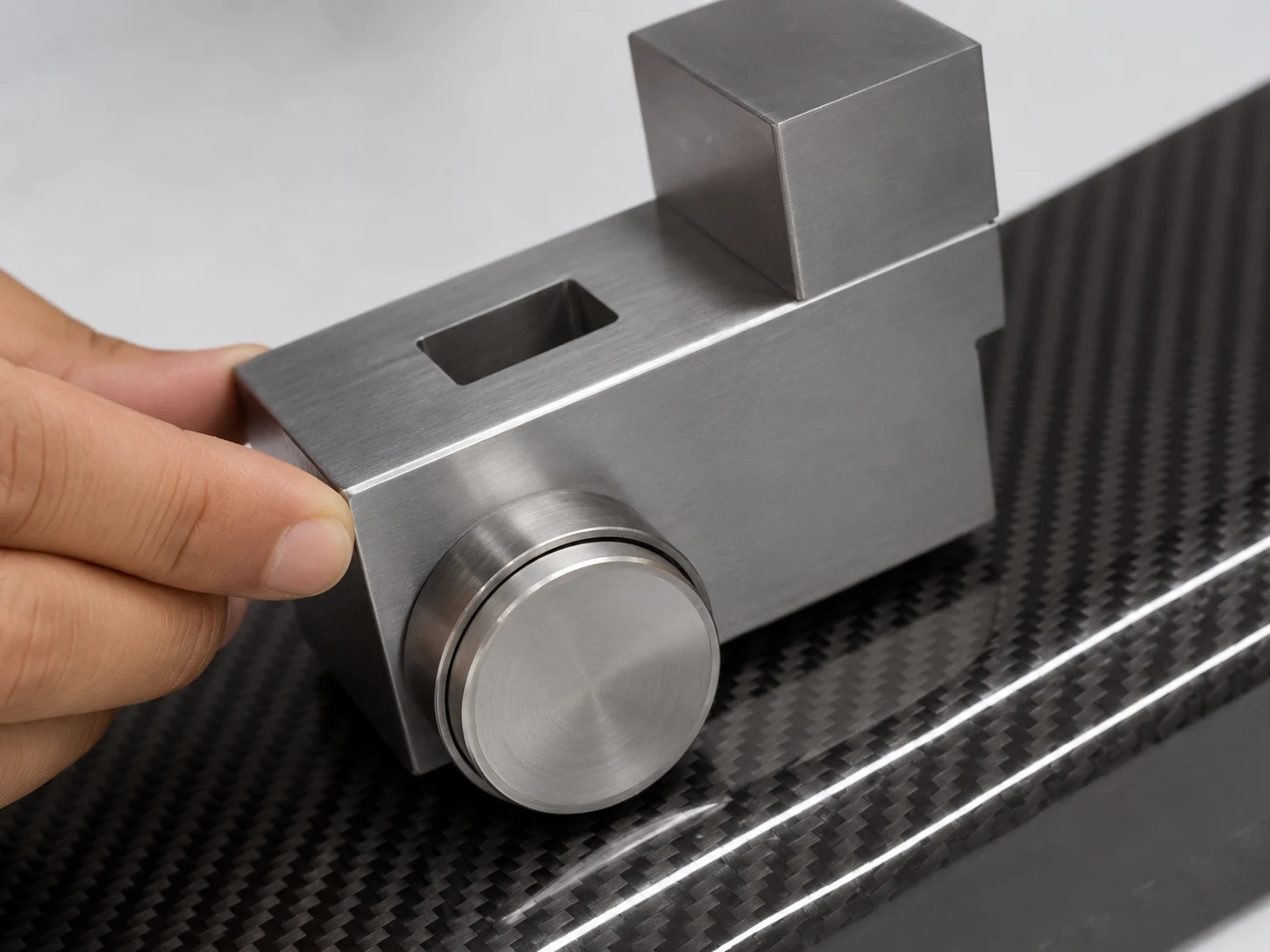
NEXWAVE first links each critical-to-quality characteristic (CTQ) to the stage where it can be prevented or verified. The method, coverage, sensitivity or measurement basis, acceptance source and release evidence are then agreed for the project.
| CTQ or result | Prevention or control stage | Suitable verification example | Acceptance source | Buyer-facing result |
|---|---|---|---|---|
| Datums, flatness and machined features | Tooling, cure and CNC datum control | Dimensional tools or CMM where suitable | Approved drawing and measurement basis | Parts can enter the intended assembly without an avoidable hole or datum mismatch |
| Thickness and weight | Material, layup/charge and forming control | Thickness and weight measurement | Drawing, laminate requirement or approved plan | Delivered parts can be checked against the stated mass and section requirements |
| Inserts, interfaces and fit | Layup, machining, bonding and assembly definition | Position, dimensional, visual or mating check | Interface drawing, assembly definition or approved sample | The component arrives ready for the agreed downstream interface |
| Internal condition | Material, layup, vacuum and forming/cure control | Ultrasonic C-scan when appropriate | Project-defined method, sensitivity, coverage and limit | Hidden indications are judged against a defined project rule, not a supplier’s opinion after the result |
| Visible surface, coating, gloss and color | Tool surface, material placement and finishing control | Visual and applicable surface/color/gloss measurement | Surface map, master sample or project criterion | The received visible part is less likely to require sorting, touch-up or refinishing before sale or installation |
NEXWAVE’s inspection resources include CMM, ultrasonic C-scan NDT, thickness and weight measurement, and surface, color and gloss tools. Internal first-article inspection is required. Delivery of a full FAI/CMM report follows the quotation or quality plan. C-scan reports are retained and supplied when NDT is required by the project or named in the quality plan. Batch CoA is a standard batch shipment document; TDS/SDS is supplied on first delivery or after revision.
Final release requires the correct product and drawing version, completed applicable checks, evaluation against approved sources and closure or authorized disposition of any release-blocking result. The record set follows the agreed scope; equipment ownership alone does not define conformity.
Trace the Affected Product and
Control the Outcome
Traceability is useful only when it connects an unmet requirement to the product that may actually be affected. NEXWAVE uses the applicable material, job, production-routing, run, operation and inspection records to identify and contain product, define the supported affected scope and route the result through formal review.
The buyer-visible sequence is:
Identify and contain the result. Preserve the condition and stop uncontrolled movement or release.
Define the affected scope. Connect the issue to the relevant material, tool/load, job, operation, part or batch evidence.
Review the requirement and authority. Establish what was not met and whether internal or customer approval is required.
Execute the authorized outcome. Repair, rework, concession, scrap or another controlled result follows the project route.
Verify any corrected or resulting state. Complete the required reinspection, revalidation or customer review.
Release or keep non-released. Only an authorized released result can proceed to delivery or a later-order baseline.
SCOPE 08-A · PINHOLE INSPECTION CHANNEL — 120-PART BATCH · ANONYMOUS JULY 2026
47 OF 120 PARTS EXCEEDED THE PROJECT PINHOLE LIMIT — ISOLATED UNDER THE FORMAL NONCONFORMANCE ROUTE.
A 120-part batch contained without redefining acceptance
In an anonymous July 2026 molding batch, final inspection stopped 120 parts after 47 exceeded the project’s pinhole limit. The parts were isolated under the formal nonconformance route. Thirty-two mildly affected parts followed a customer-approved repair, refinishing and 100% reinspection path; 15 severely affected parts were scrapped. The disposition was completed in early August, and the work instruction was updated with an added ply-count check. The project-specific pinhole threshold remains confidential.
The event did not turn a repair decision or a scrap decision into “acceptance.” The repaired parts required the approved work and reinspection before their resulting state could be released; scrapped parts remained non-released. Applicable NCR/CAR records are supplied when a real nonconformance requires customer approval or concession, while other internal Quality records remain governed by the agreed quality-plan scope.
Repeat the Released Part State,
Not Just the Purchase Order
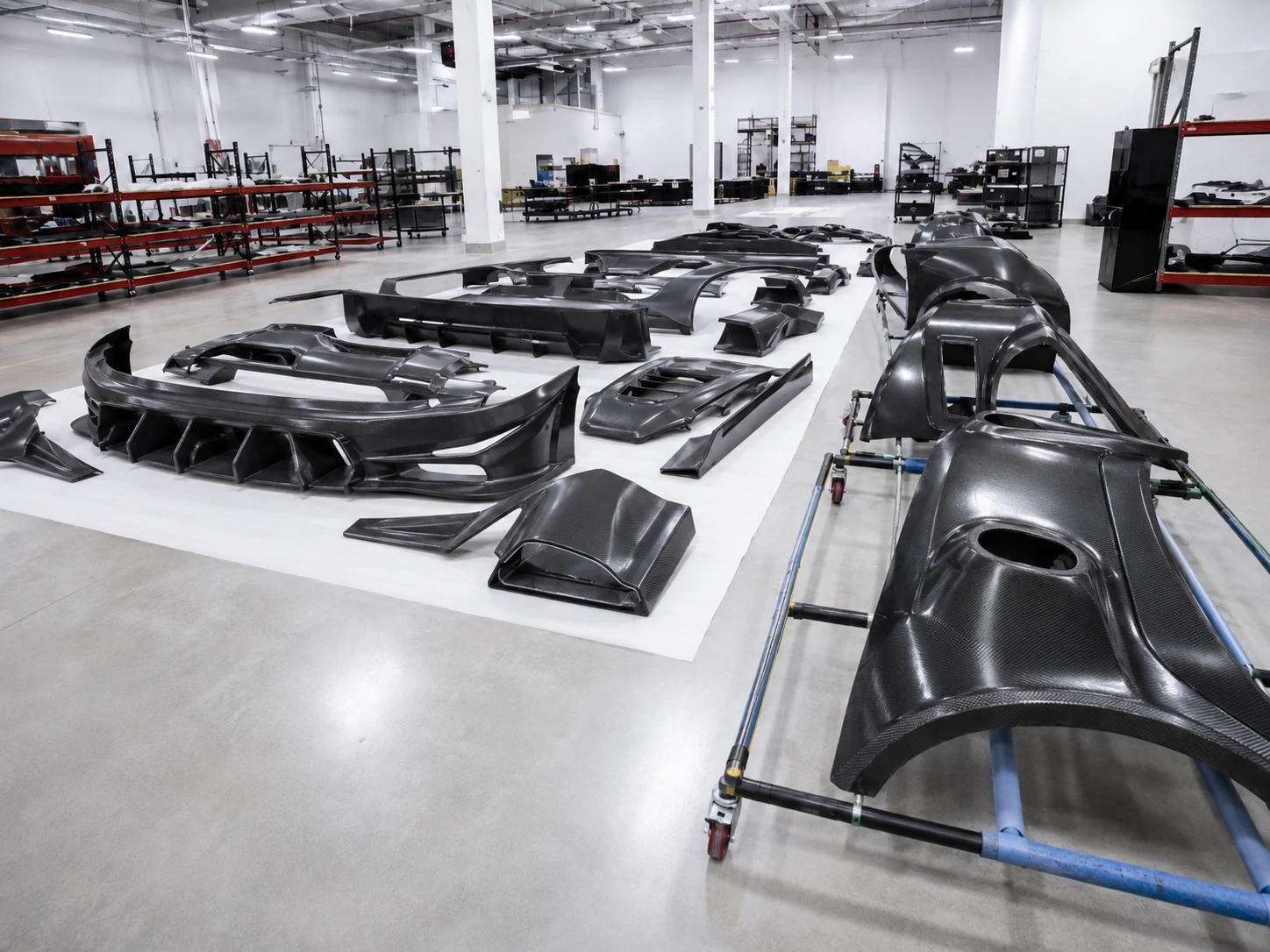
A repeated PO number cannot preserve fit, finish or acceptance. The next order must carry forward the approved material/source rule, tool and fixture version, work definition, program, drawing and interfaces, approved sample or first article, CTQs, inspection plan and released resulting state.
| Baseline item | Change that triggers review | Risk if the change is silent | Required response may include |
|---|---|---|---|
| Material grade, form, resin system or approved source | Substitution, source change, shelf/condition concern or document revision | Laminate, cure, surface or performance drift | Engineering review, updated evidence or revalidation |
| Tool, fixture or datum scheme | Repair, wear, modification or new fixture | Geometry, hole, edge, fit or surface shift | Tool/first-part check and affected CTQ review |
| Program or work definition | Cure/forming, CNC, bonding, finishing or inspection revision | Process or downstream result no longer matches the approved state | Controlled revision and impact-based verification |
| Drawing, interface or visible-surface basis | Engineering change, mating-part change or new finish requirement | Delivered part fits the old definition, not the current product | DFM, revised validation and customer approval as applicable |
| Approved sample, CTQ or inspection plan | Acceptance or method change | Later orders cannot be compared on the same basis | New approval, first-article or method review |
| Released resulting state | A deviation, repair or correction changes the part state | An exceptional result is copied without proving it is acceptable to repeat | Required disposition, correction, verification and explicit baseline authorization |
Repair, rework, concession, scrap or another controlled outcome does not itself become the repeat baseline. Only a resulting part state that has completed the required disposition, correction, reinspection or revalidation—and has been authorized for release and baseline continuation—can be carried forward.
TRACE 09-A · 22-MONTH REPEAT PROGRAM — 16 BATCHES ON ONE RELEASED BASELINE
One anonymous repeat program ran for 22 months across eight orders and 16 batches through June 2026. Within that program and measurement scope, the customer-authorized public results were above 95% first-pass yield and 100% on-time delivery. Controls included 100% mass and appearance checks with sampled CMM and thickness measurement. When a thickness departure affected one batch, the product was isolated and fully reinspected, the process sheet and pressure setting were revised, and customer engineering reapproved the change before the baseline continued.
Qualify the Control System,
Not the Equipment List
A supplier shortlist should match evidence to the risks of the current part. Similar equipment and a quality certificate can support the review, but they do not prove that a supplier has defined your route, interfaces, acceptance evidence or repeat baseline.
| Buyer risk | What to ask NEXWAVE | Evidence or boundary to verify |
|---|---|---|
| Wrong route appears after tooling | Which part conditions selected and eliminated the candidate routes? | DFM/route rationale, open conditions and validation priorities ▸ Verifiable at review |
| Wrong input enters irreversible processing | How are material, revisions, layup/charge and pre-cure status connected? | Applicable production-routing and pre-cure release evidence ▸ Verifiable at review |
| Machine status hides a part/tool departure | What defines the process window and what triggers escalation? | Material/TDS basis, program revision, monitored part/tool/run state and review status ▸ Verifiable at review |
| Post-cure work changes fit or finish | How are datums, interfaces and surface zones carried downstream? | Drawing/program/fixture/surface basis and staged verification ▸ Verifiable at review |
| Inspection does not answer the real acceptance question | Which CTQs, methods, criteria and report scope apply? | Quality plan, method boundary and authorized release evidence ▸ Verifiable at review |
| One issue disrupts the entire order | Can records define affected product and authority? | Trace path, containment, applicable formal outcome and released/non-released status ▸ Verifiable at review |
| Later orders drift from the approved sample | Which baseline items are versioned and what changes trigger reapproval? | Material/tool/program/drawing/CTQ baseline and change-response rule ▸ Verifiable at review |
NEXWAVE’s current support includes five autoclaves, five hot presses, five-axis CNC machining, CMM and ultrasonic C-scan resources, six composite-material engineers, four process engineers, five Quality personnel and approximately 35 production personnel. NEXWAVE operates a factory-wide ISO 9001:2015 quality-management system and an AS9100D aerospace QMS; its IATF 16949 automotive quality-management framework is applied to designated customer projects. These are organization and resource facts—not product certification, market approval or proof that a particular route fits your part.
The stronger proof is the connection between your part risk and the supplier’s answer. That gives procurement a defensible reason to include or exclude NEXWAVE from the RFQ, rather than relying only on a machine photograph, certificate logo or lowest headline price.
Start With the Information
You Already Have
You do not need a complete production definition for an initial manufacturing review. NEXWAVE can begin with written project information based on a CAD model, dimensioned drawing, sample, photographs or a clear part concept. The preliminary review is not a final quotation or product release.
Useful starting information
- Part function, intended environment and known load or interface conditions
- CAD/drawing revision, photographs or a sample description
- Target material or performance basis, if already specified
- Critical dimensions, datums, holes, inserts, bonds and mating interfaces
- Visible and non-visible surfaces, texture, gloss, color or finish expectations
- Prototype, validation and repeat-order quantities
- Required inspection, NDT, report, approval or packing conditions
- Destination, trade/document needs and confidentiality requirements
What NEXWAVE will clarify
- Candidate material and forming route, with the conditions that support or eliminate alternatives
- Missing geometry, DFM, tooling, interface and surface questions
- Likely post-cure operations and acceptance-critical features
- Proposed validation, inspection and record scope
- Open quotation assumptions and the next review decision
NOTE — This page does not accept file uploads. Request a written review and NEXWAVE will confirm the secure follow-up method for drawings or CAD files when they are needed.
Request a DFM
and Process Review