
Carbon Fiber Products Manufacturer for Finished Parts and Structural Forms
Choose the product route by what must arrive: a structural form, a fitted component, a molded part or a project-defined finished product.
Start With the Product Route That Can Deliver the Part You Need
“Carbon fiber” is not enough to define a purchasable product. A usable part is defined by its form, load path, interfaces, visible surfaces, supplied work and acceptance basis.
Starting from the finished result helps your team:
- — choose the right product family without guessing from a generic material name;
- — expose holes, inserts, fitment, tooling or finishing that could make a base form unusable before it is ordered;
- — see whether the quotation covers a base form, a secondary-processed product, a finished part or continuing OEM/ODM responsibility; and
- — ask for evidence that matches fit, function, appearance and the complete delivered order.
Structural and flat forms
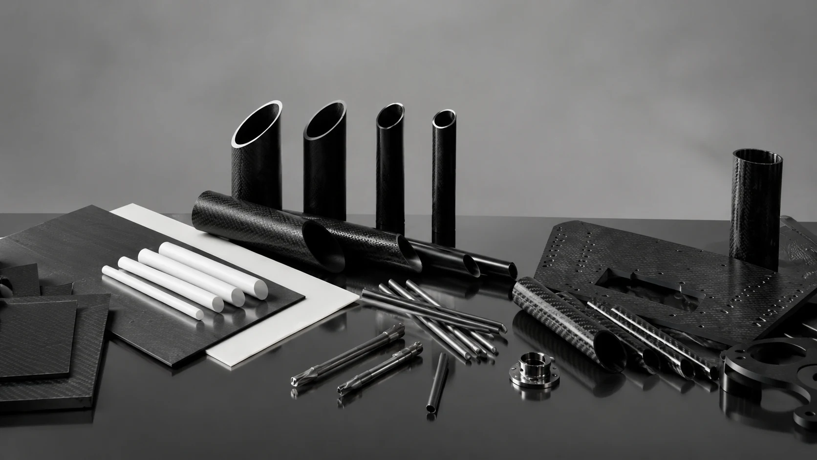
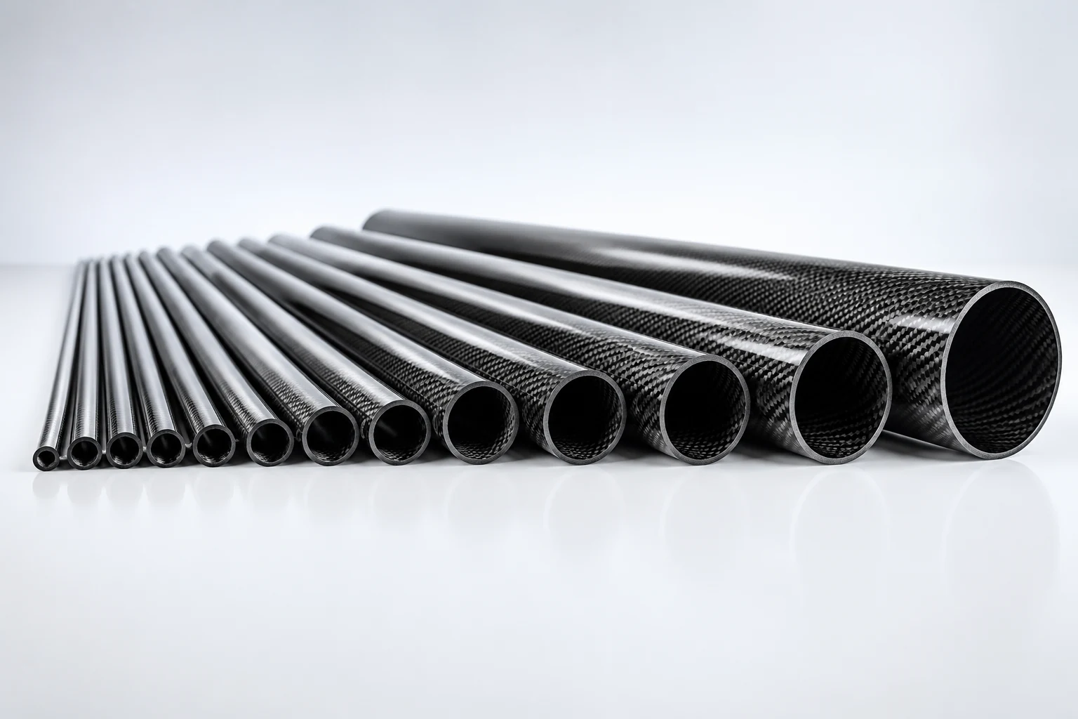
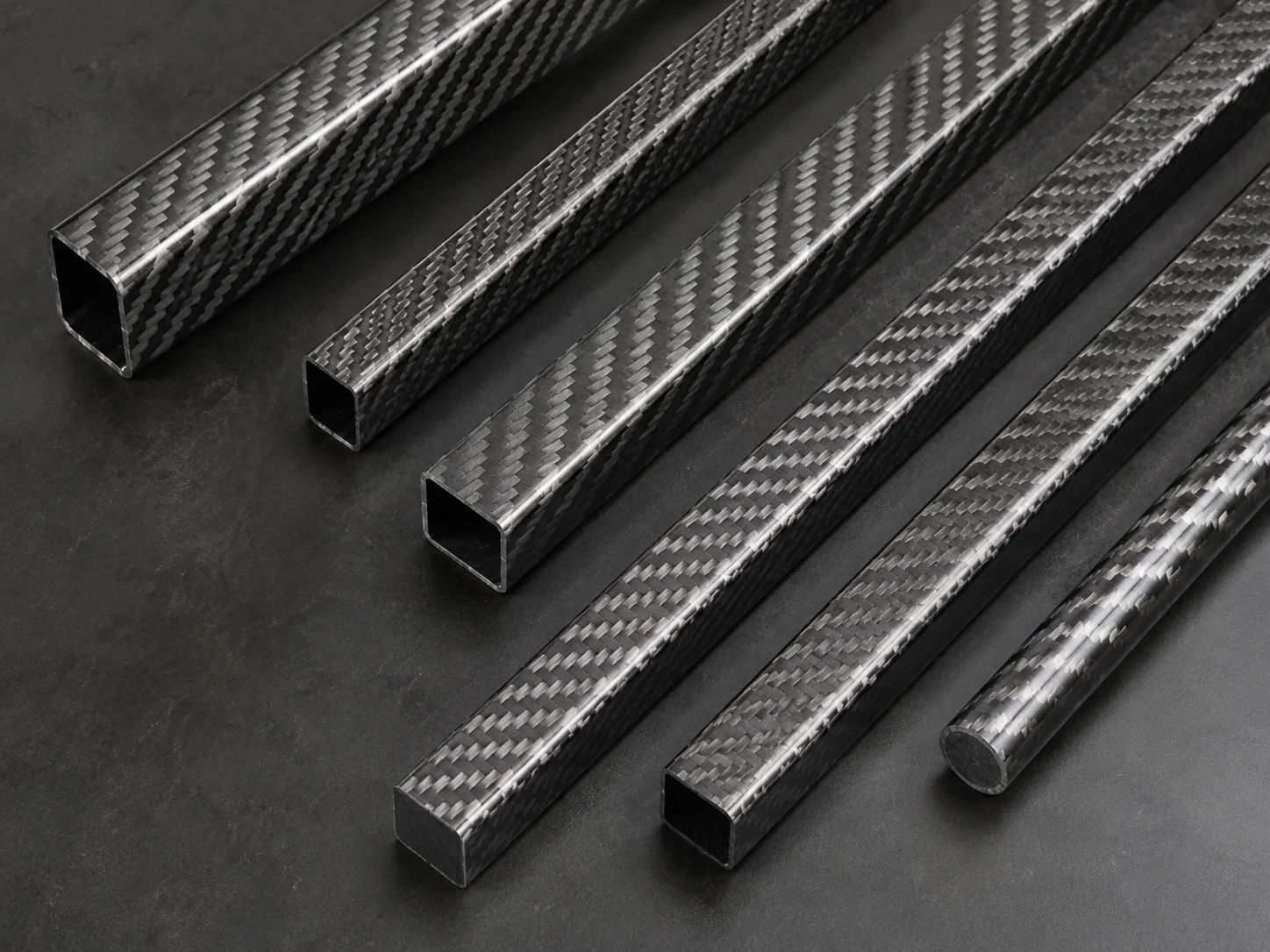
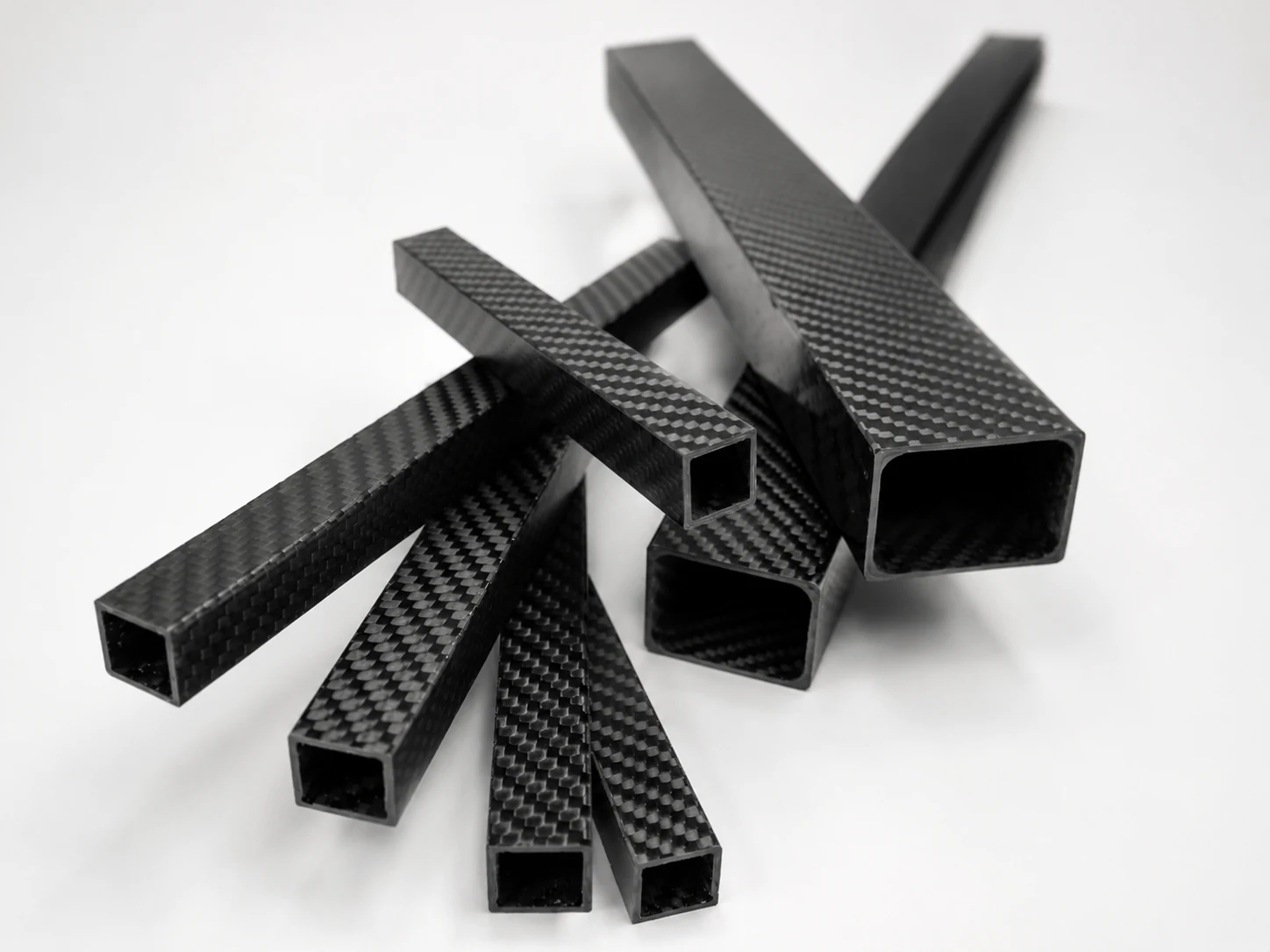
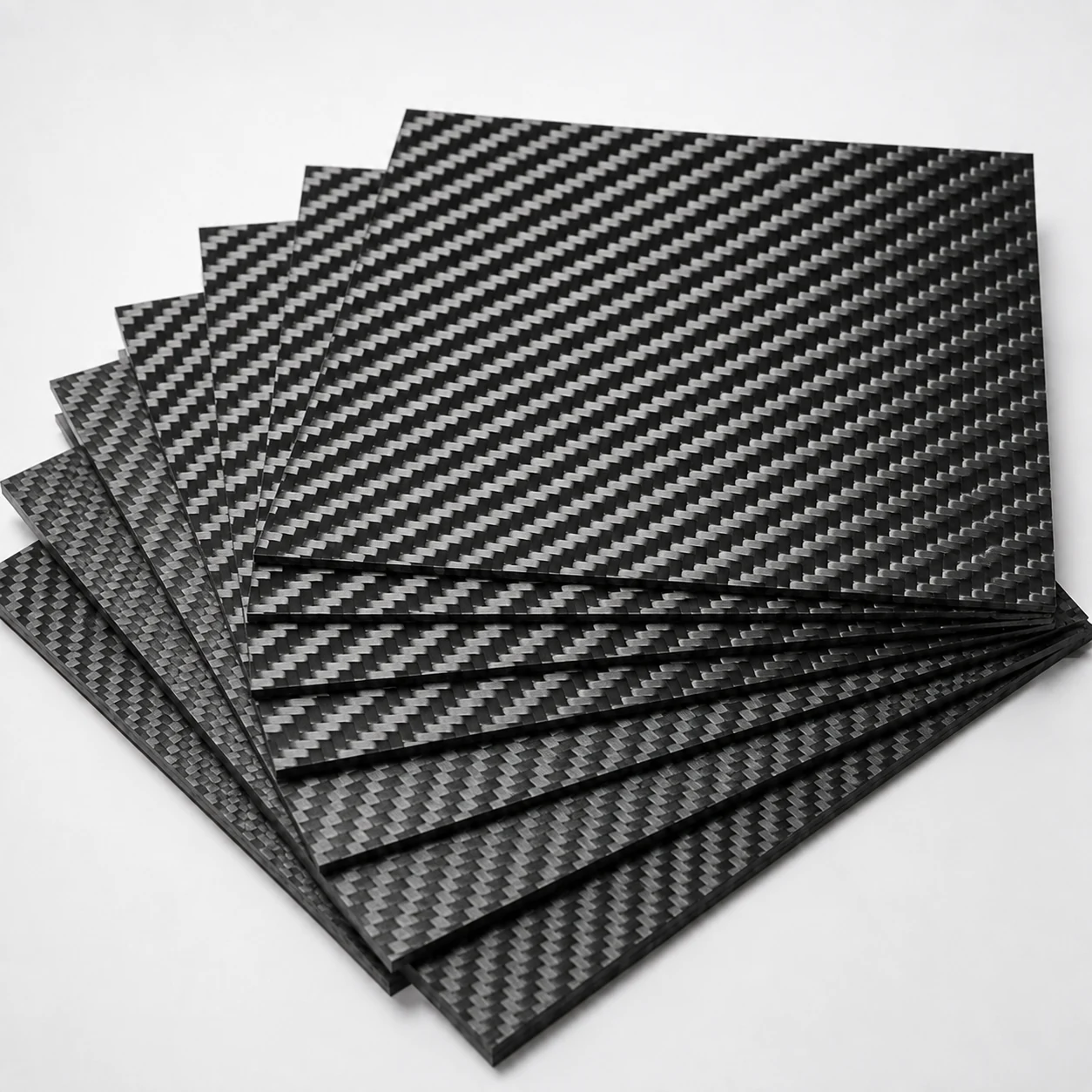
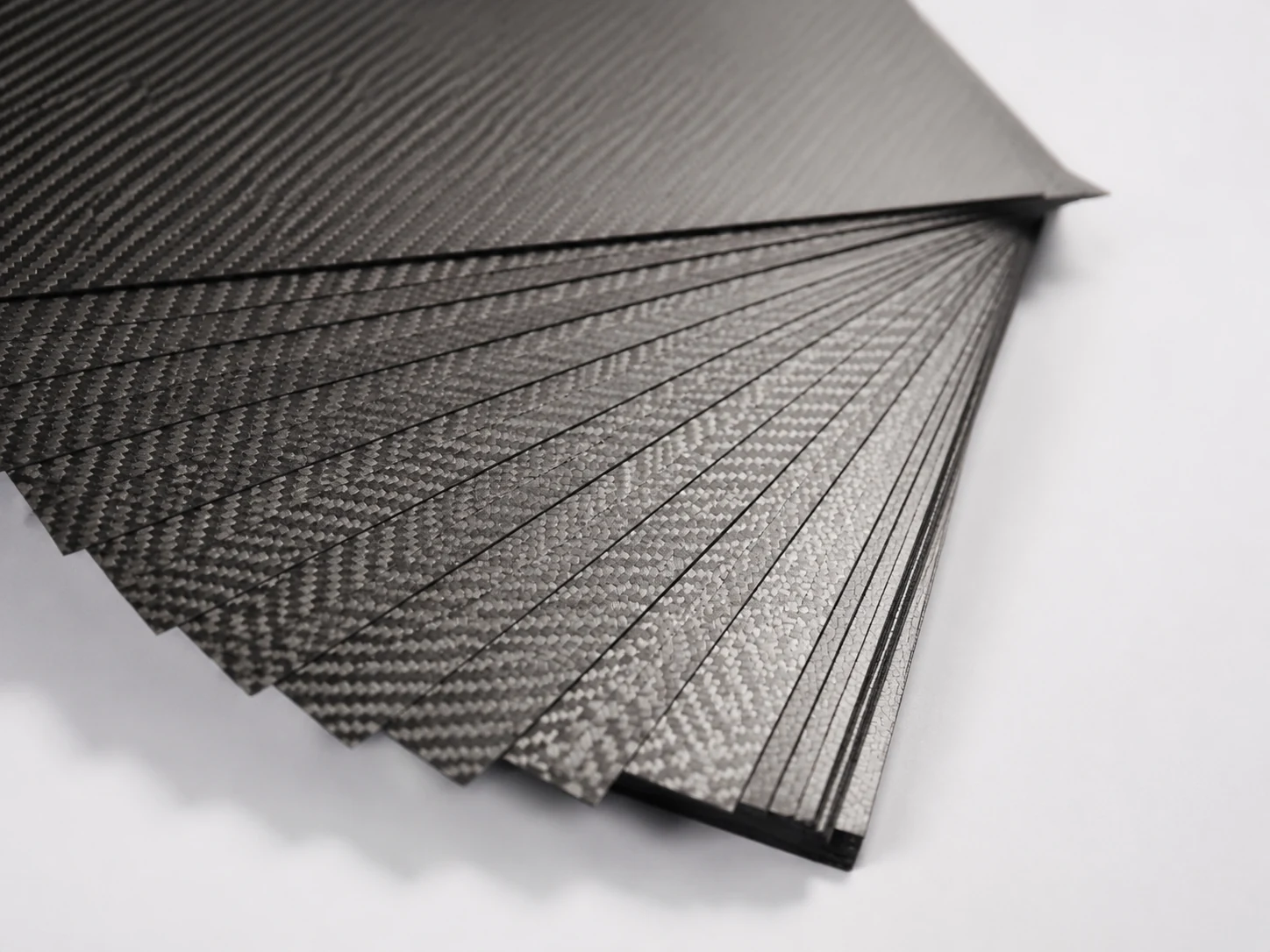
Choose Carbon Fiber Tubes for hollow round, square, rectangular, telescopic or project-defined sections. Choose Carbon Fiber Rods for solid round, square or rectangular members. Choose Carbon Fiber Profiles for constant non-round sections such as L angles, U or C channels, I or H sections and flat strips. Use Carbon Fiber Tube Connectors when the connector itself is the main sourcing requirement. Choose Carbon Fiber Panels and Plates when a sheet, plate, finished solid panel, sandwich panel or CNC-cut flat component controls the purchase.
Fitted application parts
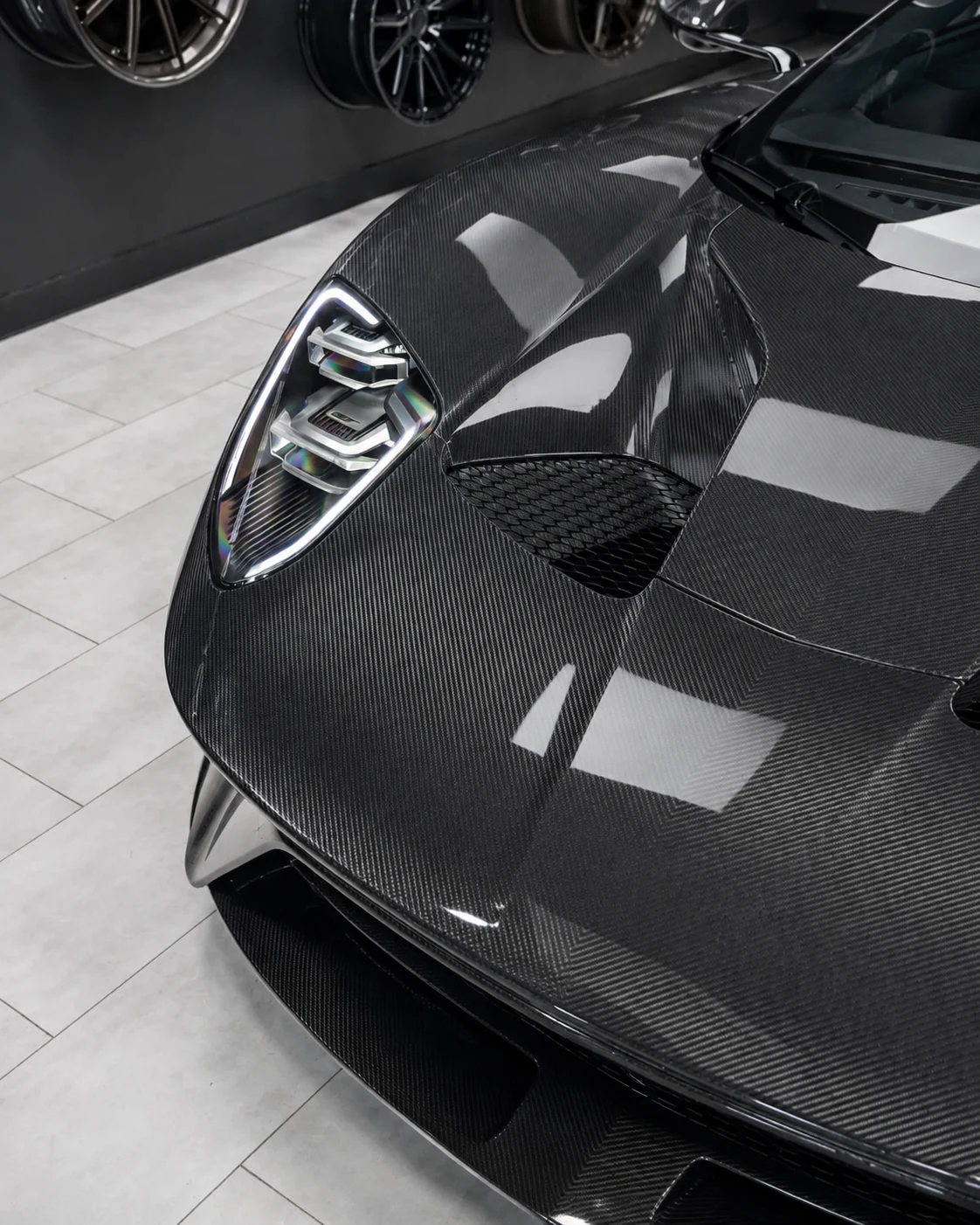
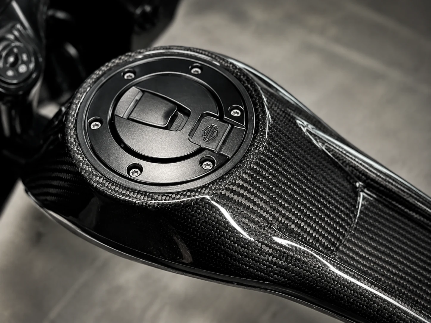
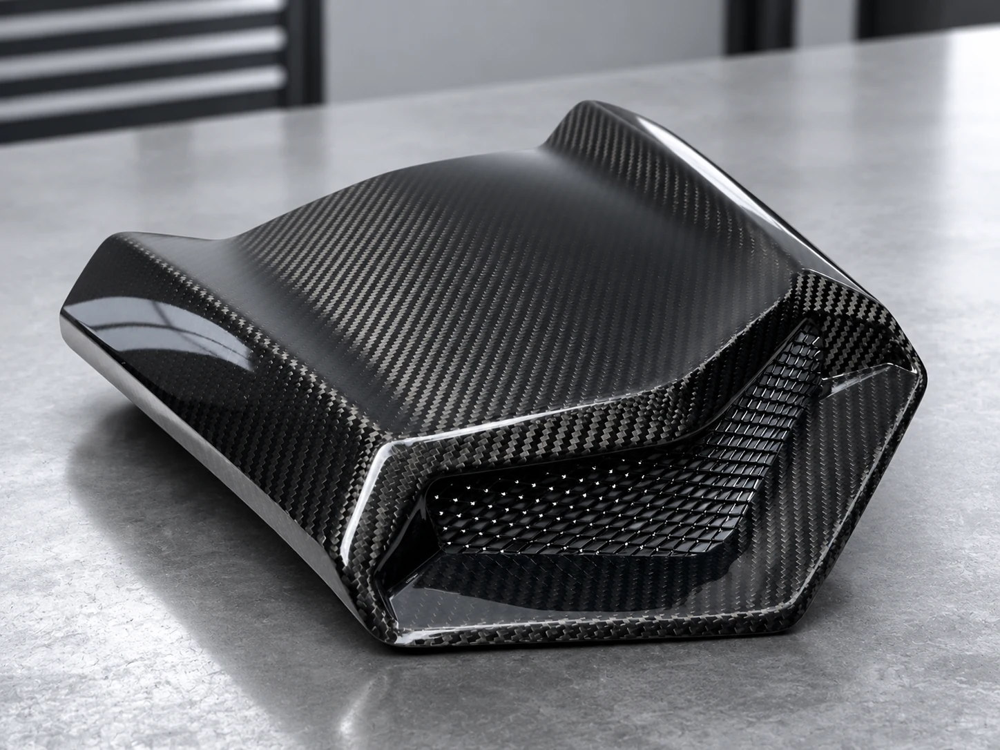
Choose Automotive Carbon Fiber Parts, Carbon Fiber Motorcycle Parts or Powersports Carbon Fiber Parts when the actual part, vehicle or equipment reference and installation interface lead the decision. These are separate application paths because mounting points, adjacent clearances, trim boundaries and validation responsibility differ.
Material and process-led form
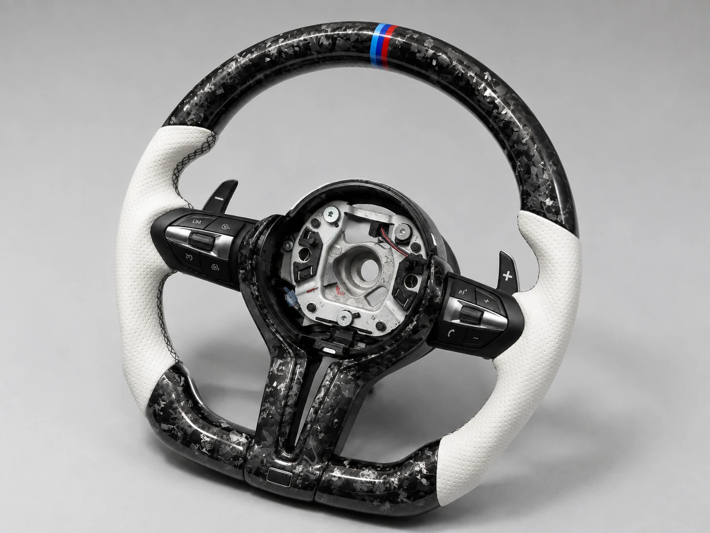
Choose Forged Carbon Fiber when chopped-fiber construction, molded geometry or the forged visual character is the primary product condition. If the part also fits a vehicle or powersports platform, begin with the relevant application and identify forged carbon as a project requirement.
Custom and continuing program responsibility
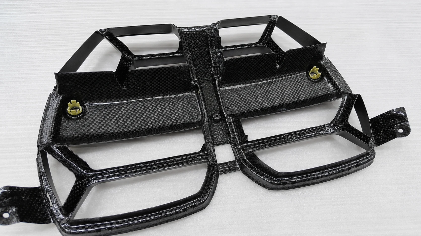
Move to Custom Carbon Fiber Parts when a drawing, scan, sample, molded geometry, inserts, bonding, finishing or assembly defines the finished component. These custom carbon fiber products begin from the controlled deliverable rather than a generic catalogue form. Use Carbon Fiber OEM Manufacturing when the work also includes branding, private-label presentation, packaging or continuing product-program coordination.
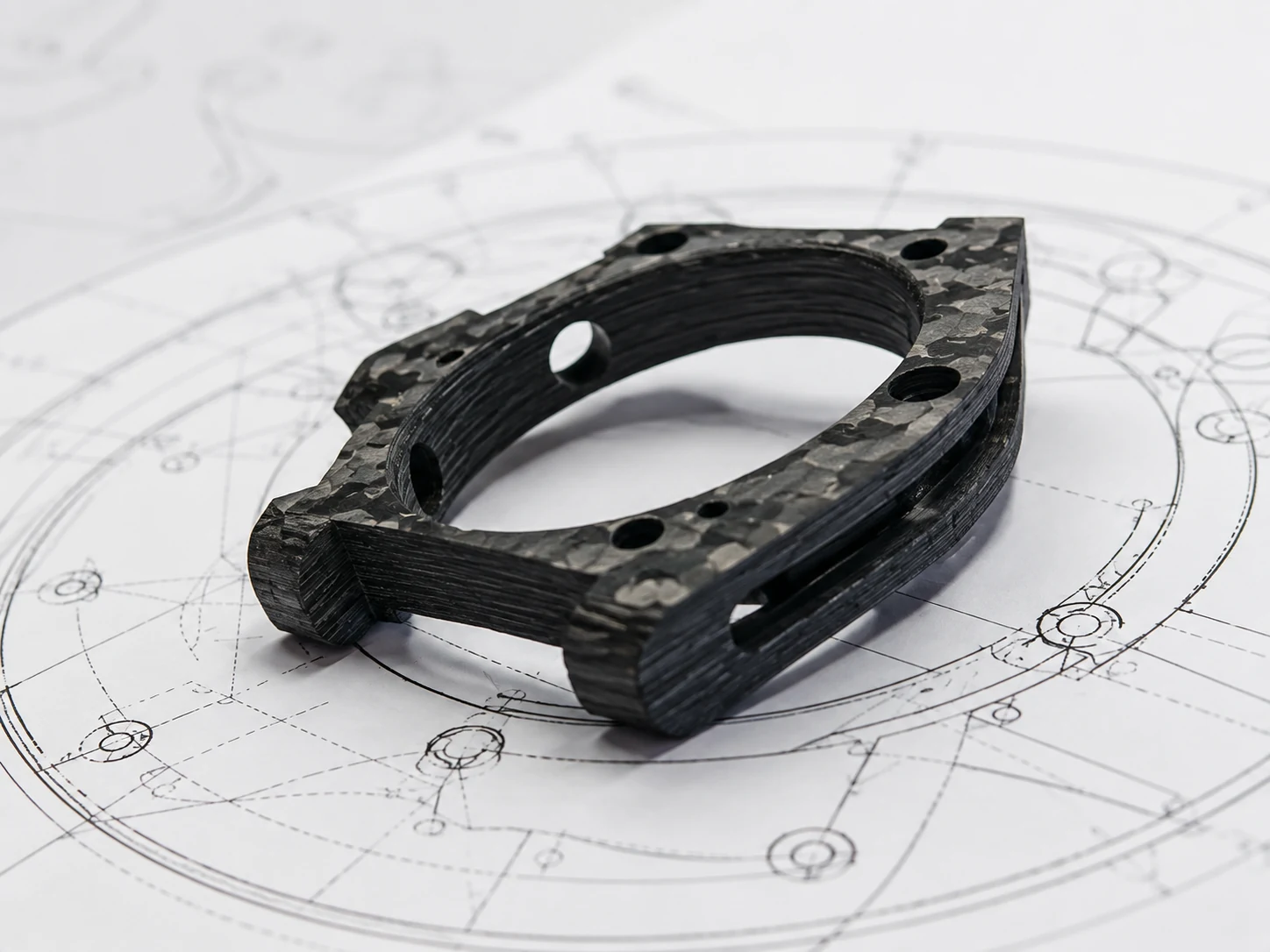
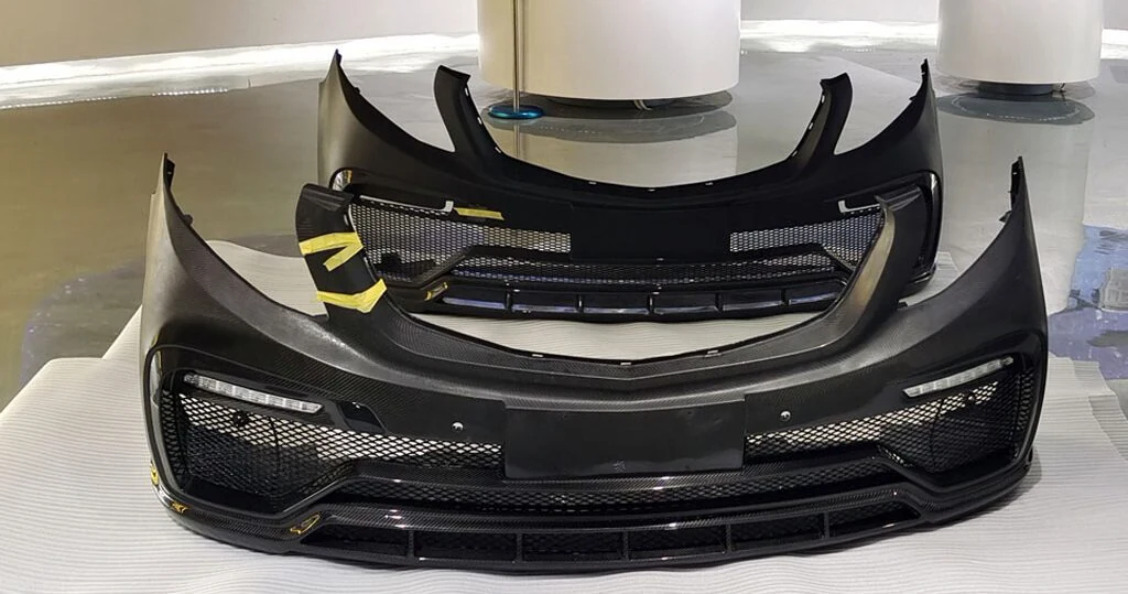
Depending on the product family, NEXWAVE may manufacture the finished product, complete approved secondary processing on a sourced base form, or coordinate a project-defined manufacturing route. The quotation identifies the exact supplied product and included work.
The product family is the first decision. Geometry, laminate, surface, quantity, tooling and acceptance requirements still determine how that product should be made and supplied.
Choose Tubes, Rods and Profiles by Section, Load Path and Interface
The cross-section may identify the family, but the local interface often decides whether the member will work in the assembly. Review the section, wall or solid condition, fiber direction, end features, holes, inserts and mating load path together.
This helps avoid drilling or joining a nominally suitable member in a way that creates delamination, poor fit or another round of machining after delivery.
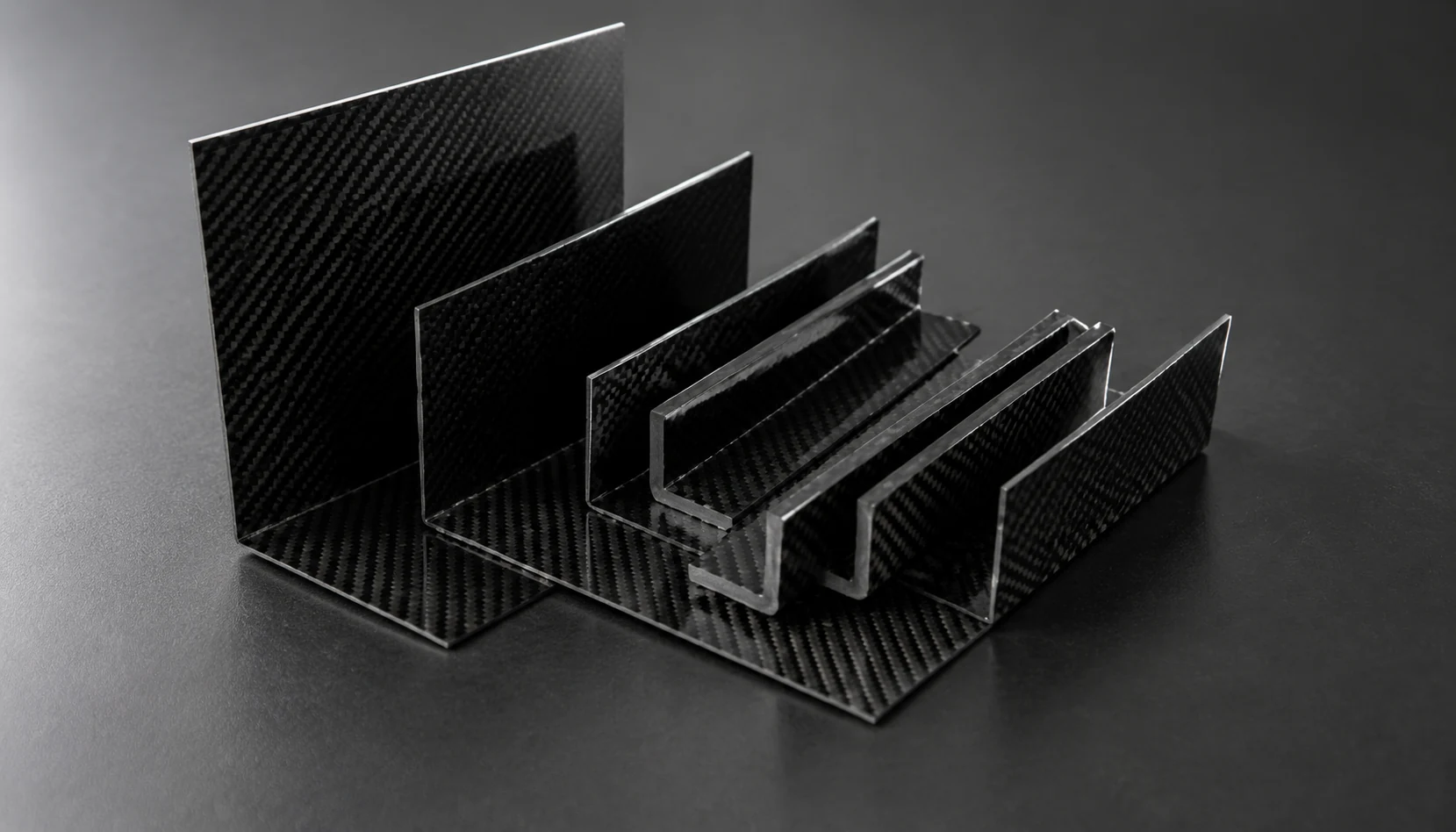
Fig. 02-A — Section stock, surface states before secondary work
Tube construction follows the requirement
Regular round-tube requirements may use approved sourced roll-wrapped, wound or pultruded base stock. NEXWAVE can then complete the quoted cutting, drilling, end work, surface work, inspection or assembly. When a project requires a non-standard diameter, wall, laminate angle, high-modulus construction or length, NEXWAVE may review in-house roll wrapping or wet filament winding. The quotation states which route applies, so the buyer is not charged for project-defined manufacture when an approved base tube and secondary work already meet the need.
Square and rectangular tubes normally begin from sourced pultruded or roll-wrapped stock before drawing-defined cutting, end finishing, CNC openings, slots, surface work and inspection. Telescopic systems begin with the required nested geometry and are reviewed as an assembly, including end steps, anti-rotation features, locking hardware and extended or collapsed length where quoted.
A drilled interface is part of the product decision
In a September 2025 UAV arm project, NEXWAVE began with sourced 3K-twill prepreg roll-wrapped tubes and completed length cutting, four Ø6 mm through-holes at the ends, chamfering, matte surface work and inspection. A standard drill initially left exit-side fiber tearing. The released method used a step drill with exit backing, followed by 100% 20× exit-face review and surface inspection, first-article and periodic CMM hole checks, and sampled OD, ID and length checks. The 240-tube batch was delivered after five surface-scratch reworks passed final review.
This is why a hole should be quoted with its location, datum, exit condition and inspection method. It is not merely a secondary note added after the tube is selected.
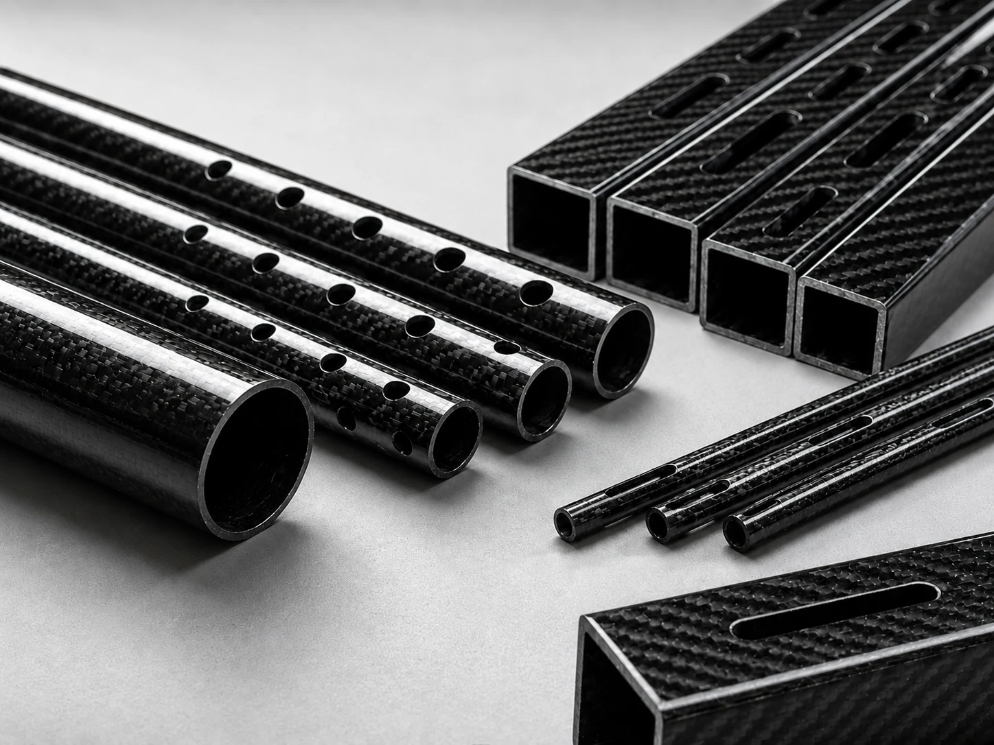
Fig. 02-B — Drilled end interface, exit-face review
Threaded connections need a load-aware route
For structural connections, the default route is a machined and installed metal threaded insert or sleeve using the project-selected bonded or mechanical-locking method. Direct threading in the CFRP wall is an exception. It starts with a wall of at least 3 mm, dedicated hoop or ±45-degree reinforcement, very low axial load and an adjustment or preload function, then still requires DFM review of geometry, engagement, environment and inspection.
Direct CFRP threads are not used under this record for power-transmission, suspension, primary load-bearing bracket or impact connections. Defining the load early keeps a convenient thread detail from becoming the weak point of the delivered assembly.
Treat the connector according to what controls the purchase
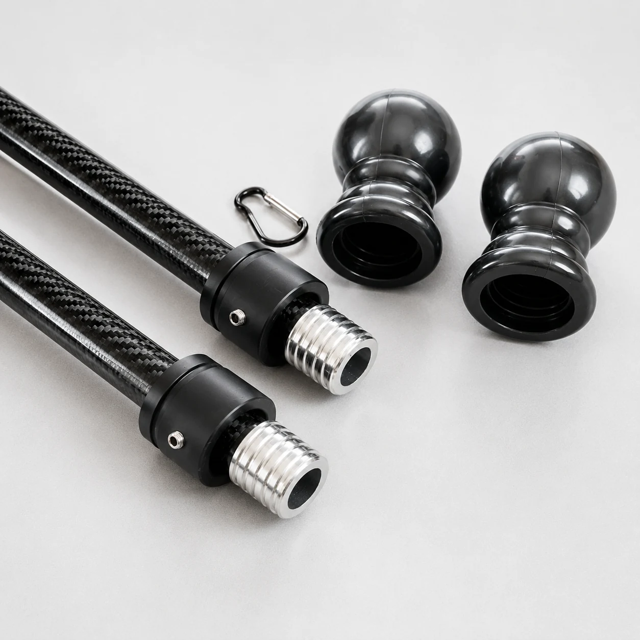
If the connector itself is the main sourcing requirement, use the Tube Connectors route. If the connector is only one interface within a tube, rod or profile assembly, include it with the structural-product review so the mating geometry, inserts, bonding or assembly responsibility can be evaluated together.
NEXWAVE can review sourced carbon-fiber, aluminium, titanium or polymer connector components with the quoted trimming, drilling, surface work, fit-up, bonding, locking or assembly. Standard inserts, sleeves and quick clamps may be supplied separately when available. Project-defined carbon-fiber elbows, tees, crosses and multi-angle connections are normally reviewed with the related tube or assembly.
Choose the Flat Product by What Must Arrive Finished
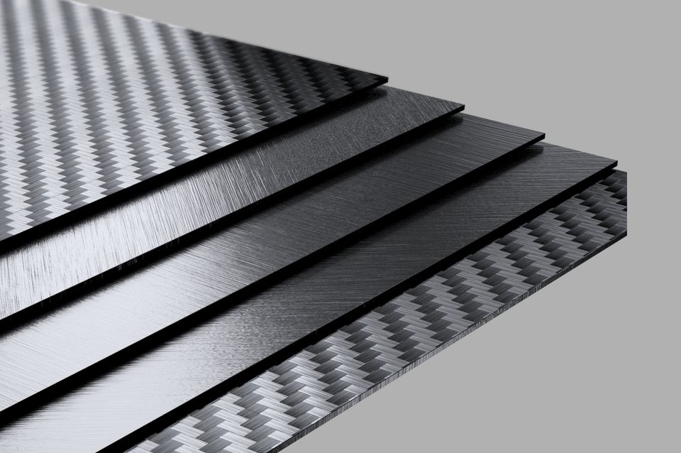
A sheet, a plate, a finished solid panel and a sandwich panel may all look like flat carbon fiber in a catalogue. They create different work at the edges, openings, inserts, visible faces and downstream assembly. Define the delivered state first so the order arrives as the blank or finished component your team can actually use.
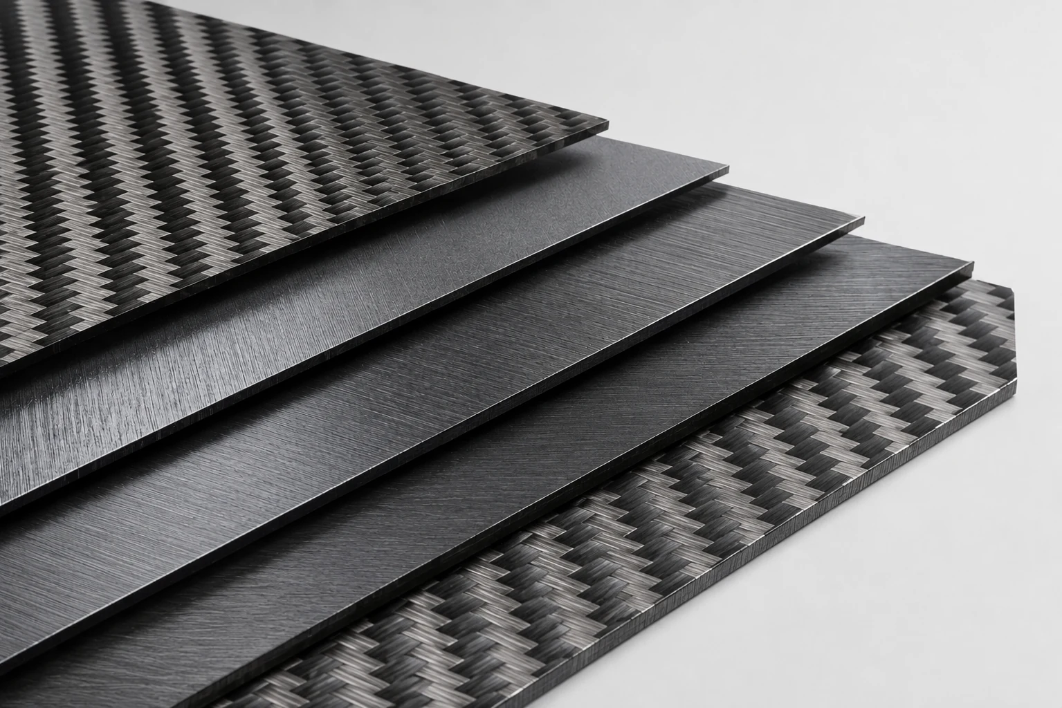
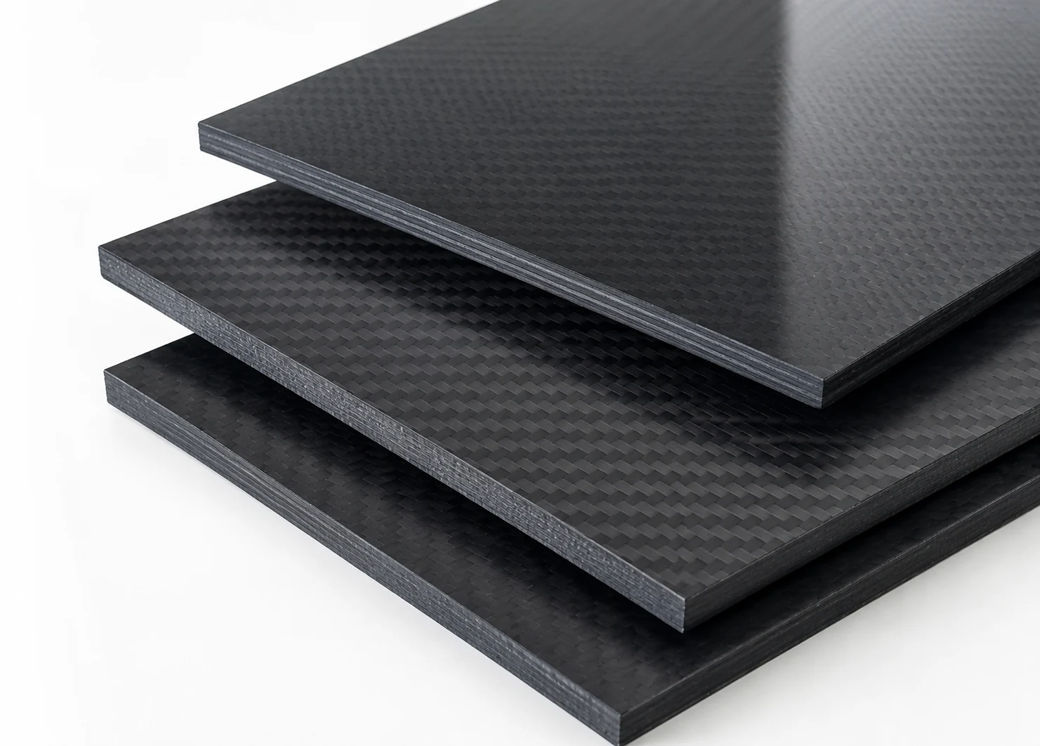
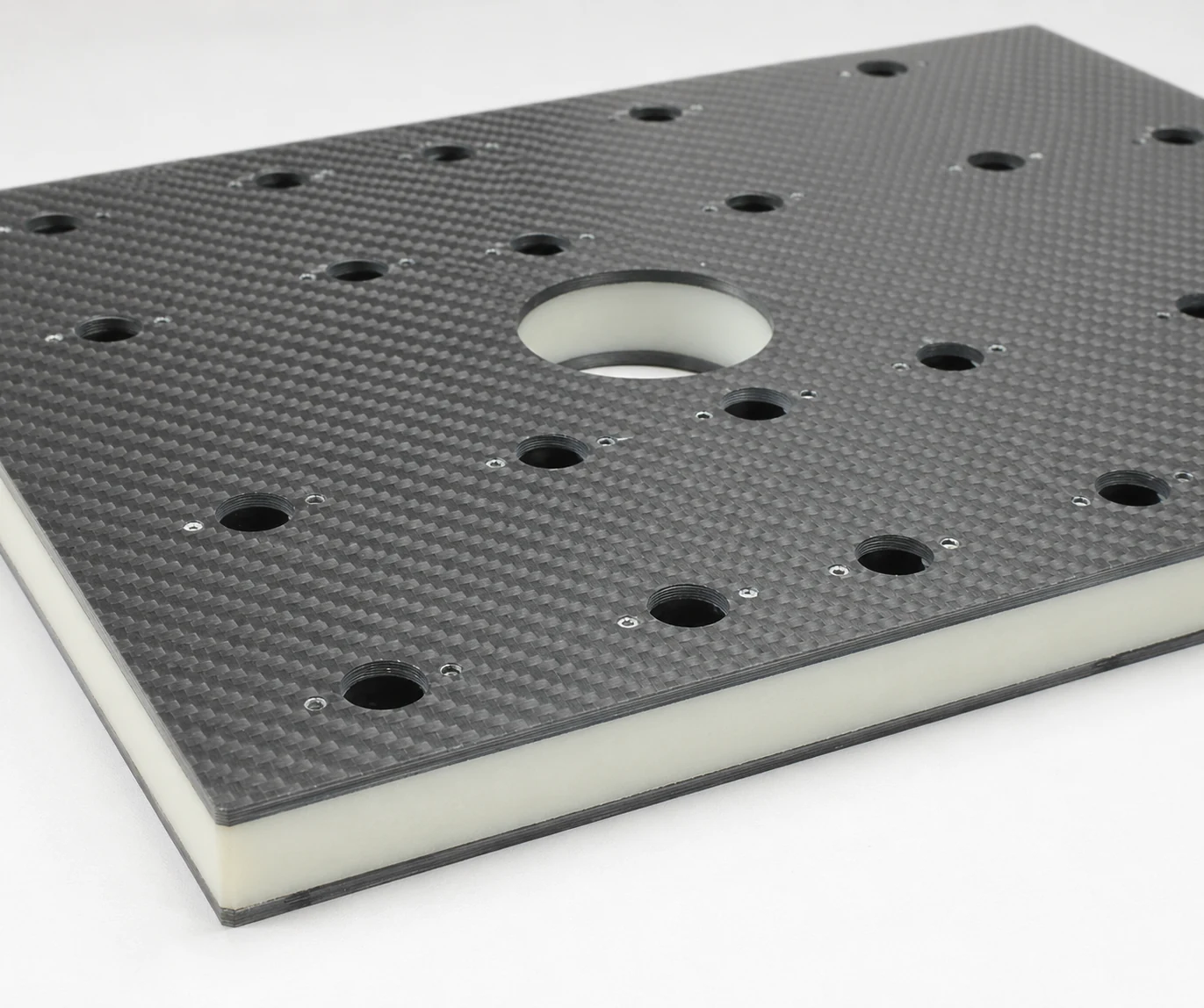
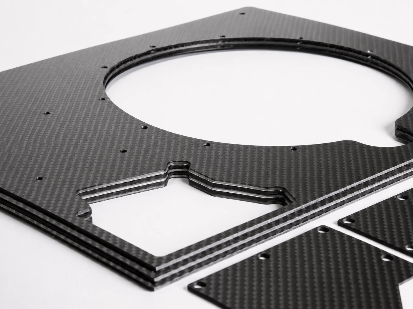
NEXWAVE manufactures cured carbon-fiber sheet, carbon fiber plates and non-sandwich solid-panel products in-house. A sandwich construction may use an approved procured core, then continue through NEXWAVE design and manufacturing work when that responsibility is included in the quotation. The source of the core and the included bonding, co-curing, machining, edge, insert and inspection work remain explicit.
For a flat product, surface protection is part of the finished state. Visible faces, large areas, cut edges and corners need product-specific film, separation, support or packing. Defining that protection before quotation helps prevent a usable laminate from arriving with scratches, edge damage or exposed core that creates sorting, refinishing or replacement freight.
Use the Installation Reference to Choose Automotive, Motorcycle or Powersports Parts
A fitted part should be selected by the real vehicle or equipment interface, not by a similar-looking photograph. The strongest starting reference is controlled CAD or a drawing, followed by an approved original part or scan. Photographs and approximate dimensions can support an early review, but close-fit work needs controlled geometry before tooling or production release.
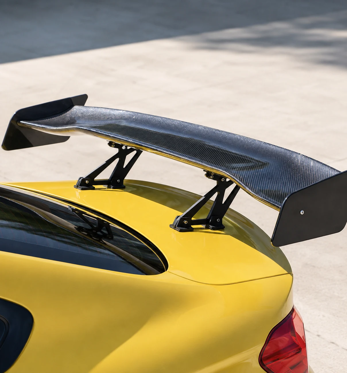
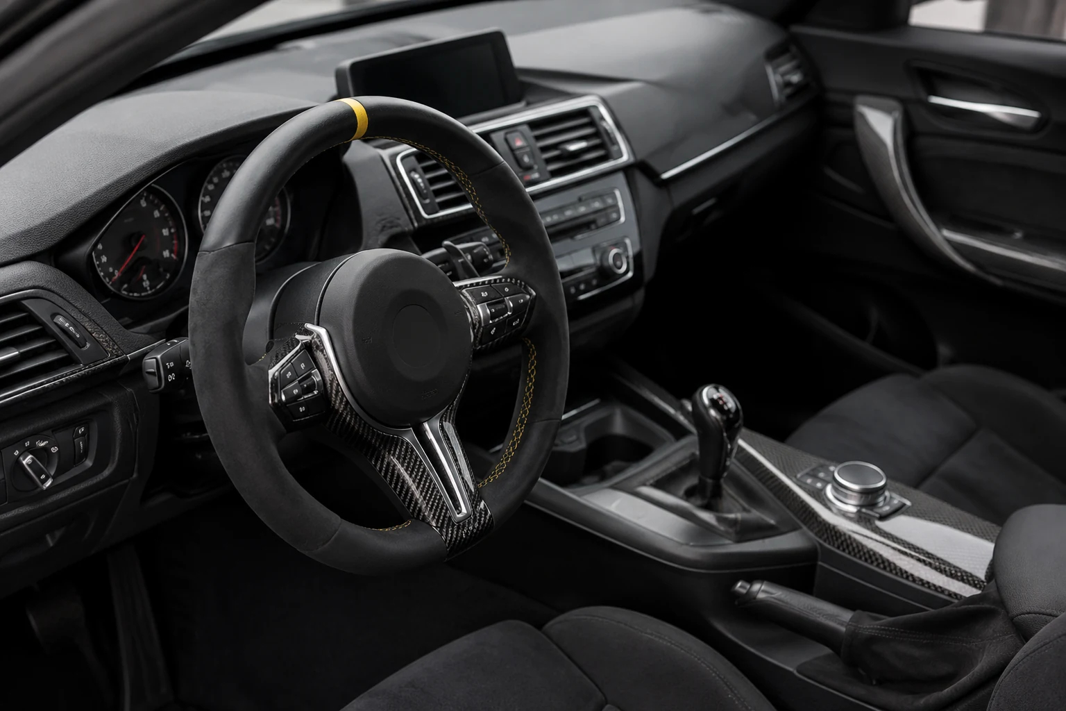
Fig. 04-A · Automotive
Automotive
Start with Automotive when the vehicle part, platform, mounting points, adjacent surfaces and visible finish control the purchase. An existing tool may shorten the route to a first article when it matches the exact vehicle configuration and part, but tool availability alone does not prove stock, installed fit or production readiness. NEXWAVE reviews the tool, geometry, interfaces, supplied hardware, finish and validation plan for the selected part.
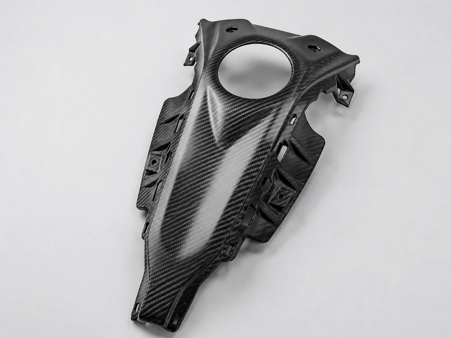
Fig. 04-B · Motorcycle
Motorcycle
Start with Motorcycle for fairings and bodywork, covers and guards, intake or airbox parts, heat-protection pieces and other fitted motorcycle components. NEXWAVE records 28 current public motorcycle references across Ducati, BMW, Yamaha, Kawasaki, Aprilia, Harley-Davidson, Vespa, Honda, Triumph and KTM. These references use NEXWAVE-controlled molds and in-house prepreg and autoclave production with a UV-protective coating.
Each order still requires the exact model year, chassis or market version, part configuration, installation condition and finish. The references are compatibility starting points, not universal direct-fit, finished-goods stock or OEM affiliation claims. Full structural frames, structural swingarms and carbon-fiber wheels remain project-review items with separate engineering, validation and release responsibility.
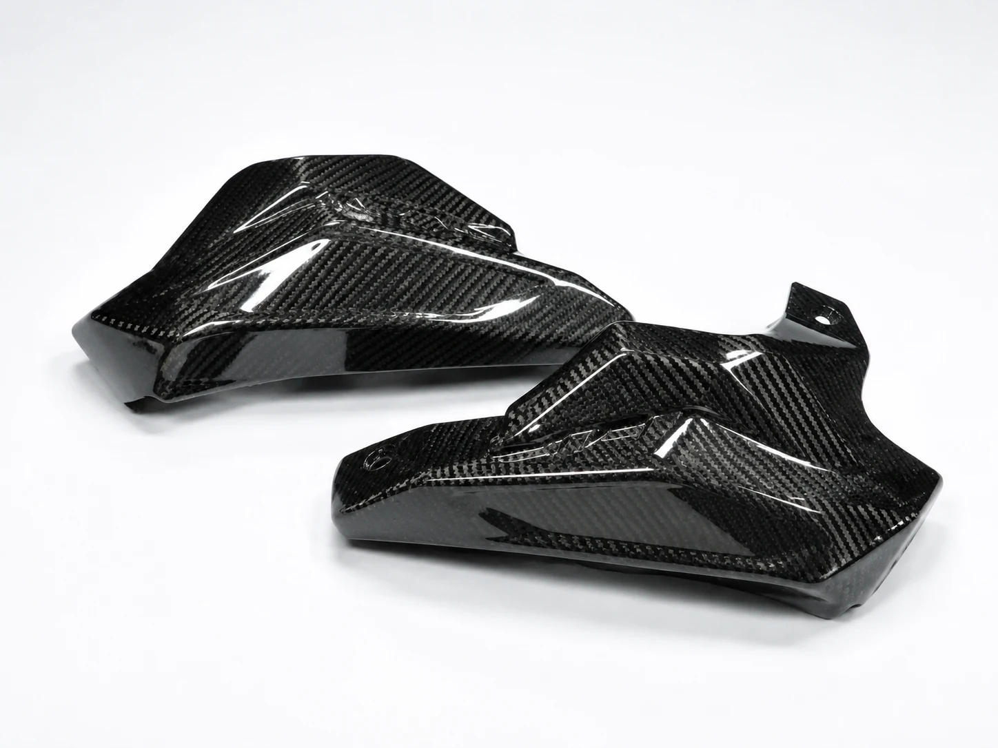
Fig. 04-C · Powersports
Powersports
Start with Powersports when an ATV, UTV or other powersports platform controls the part. Current project review can cover hoods, fascia, dashboards, instrument or switch panels, fenders, side or interior panels, doors and roofs. The buyer supplies the governing equipment or mating-part reference and approves installed fitment; NEXWAVE owns the factory work and checks assigned in the quotation.
An anonymous ATV hood project began with the original flexible plastic hood, a representative vehicle and interface photographs. NEXWAVE completed scan-to-CAD work, DFM, local reinforcement definition, prepreg layup and autoclave cure, CNC grille and edge work, clip preassembly, vehicle fitment, clear-coat application and inspection. Steel tooling and standard clips were sourced.
The first sample showed an approximately 1.8 mm front clearance against a project target of no more than 1.0 mm. A +0.6 mm tool-surface correction produced a second sample at 0.8 mm, which the customer’s engineering team approved on the vehicle. Two first-article sets were followed by a 60-set order. The correction happened before batch delivery, avoiding sixty hoods with the same visible fit issue.
Fig. 04-D — Front clearance, sample 1 → sample 2 after +0.6 mm tool-surface correction
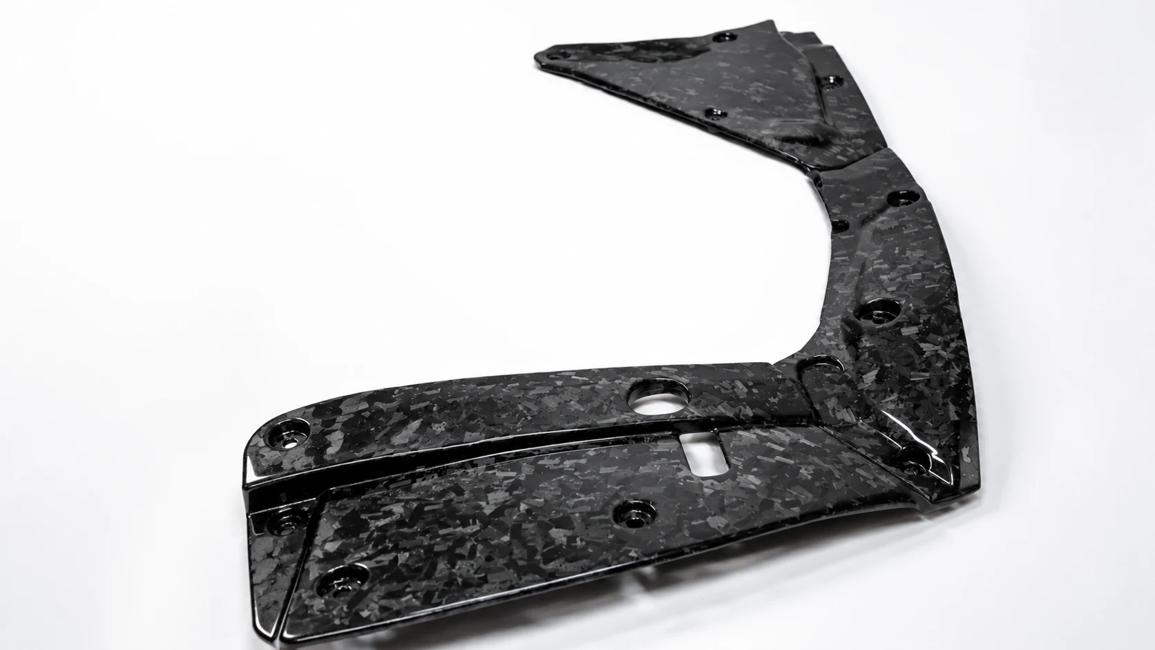
Use Forged Carbon When Chopped-Fiber Geometry or Appearance Leads
Use Forged Carbon when chopped-fiber construction, molded geometry or the forged visual character is the primary product requirement. NEXWAVE reviews the chopped-fiber material, mold, pressure and heat route, finished geometry, structural role, visible surface and required validation as one project. Two recorded forged-carbon forming machines support this work, but the equipment itself does not establish the performance of a finished part.
When the part is also automotive, motorcycle or powersports, start with the application route and identify forged carbon as a construction or appearance requirement. That gives the buyer one review for fitment and molded construction instead of two unexplained entry points.
Forged appearance is not a structural rating. If the part carries load, the geometry, material definition, load path and validation basis must be agreed separately. This keeps a surface preference from being mistaken for proof that the delivered part can perform a structural function.
forming machines
Decide Whether the Deliverable Is Standard, Modified, Custom or OEM/ODM
Choose the least complex supply route that still delivers the required finished product. This keeps straightforward secondary work from turning into unnecessary tooling, while making sure a drawing-defined part is not treated as an off-the-shelf form.
Standard
Standard product
The agreed tube, rod, profile, sheet, plate or panel in its base condition
Use It WhenThe existing form and supplied state already fit
Modified
Modified standard product
An approved base form plus quoted cutting, holes, slots, countersinks, edges, surface work or interfaces
Use It WhenSecondary work can create the finished state without redefining the base product
Custom
Custom part
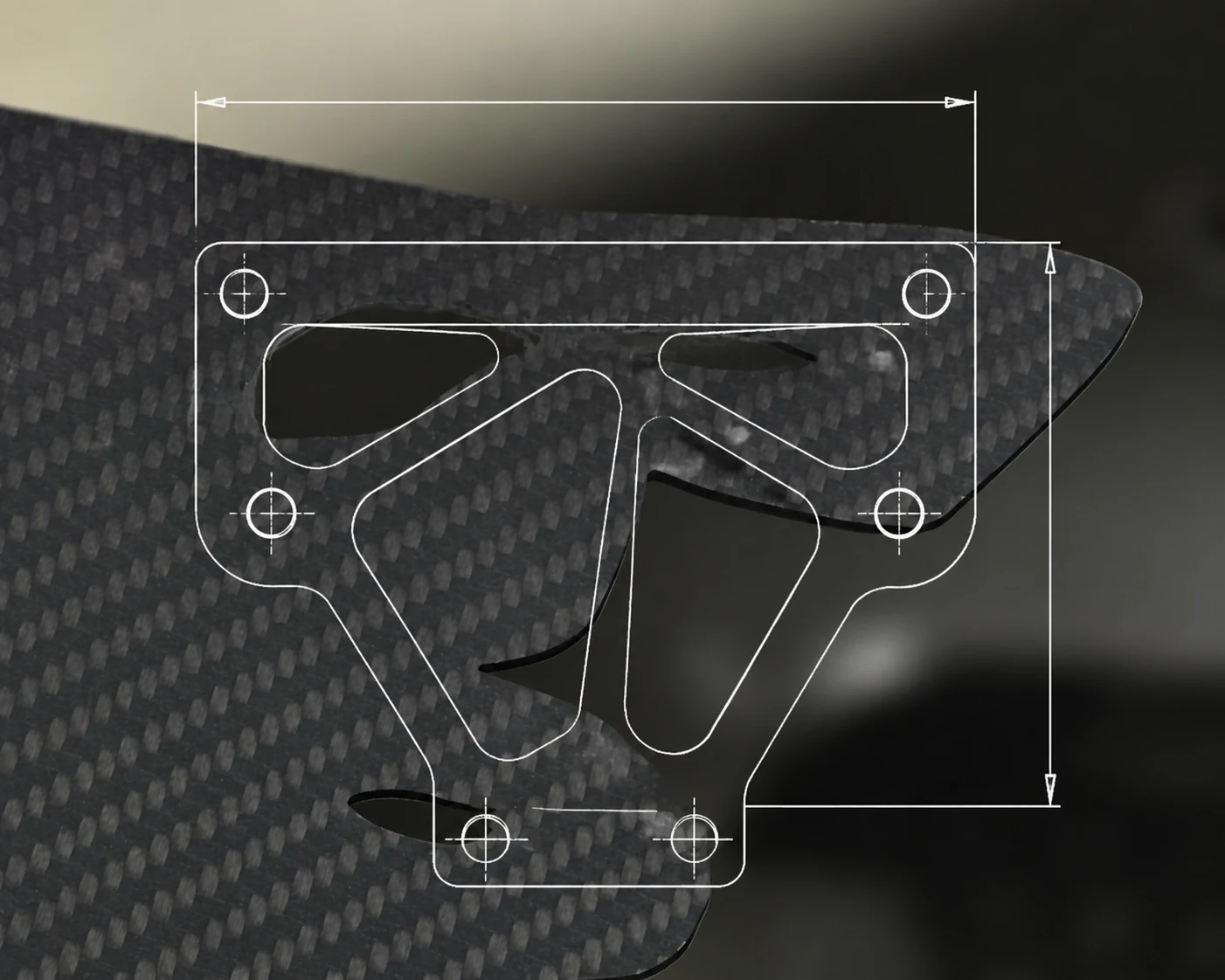
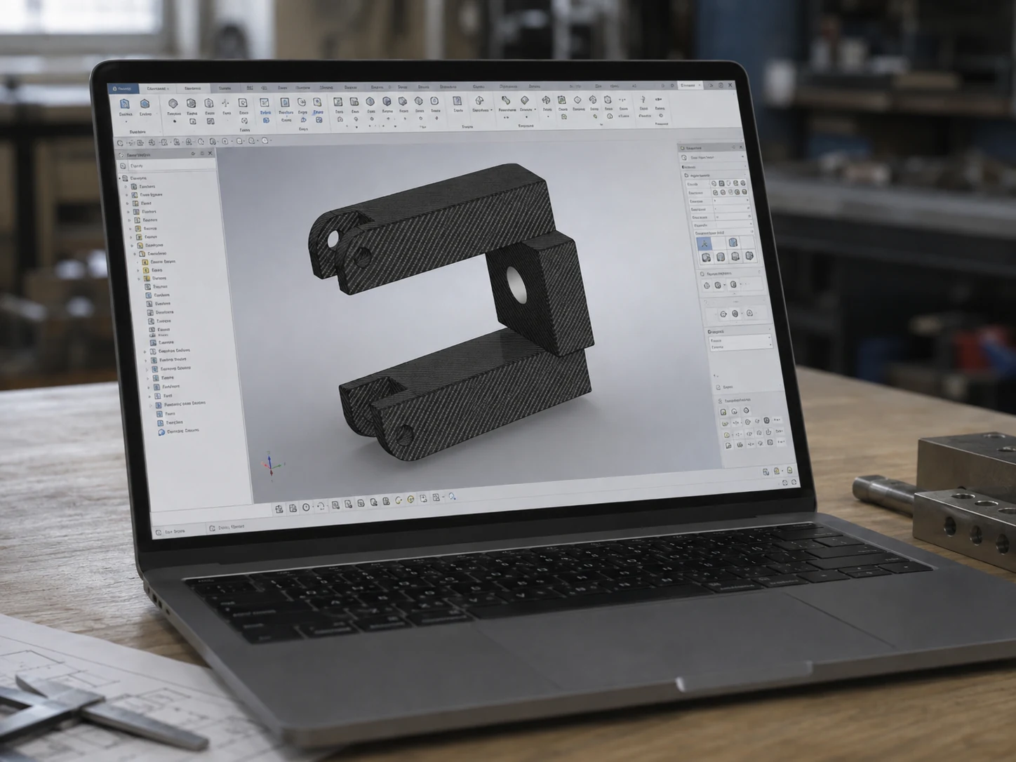
A drawing-, scan- or sample-led part with project-defined molding, machining, inserts, bonding, finish or assembly
Use It WhenGeometry, tooling, laminate or validation defines the component
OEM · ODM
OEM/ODM program
A finished part plus agreed branding, labeling, packaging or continuing coordination
Use It WhenNEXWAVE responsibility continues beyond part manufacture
Product form does not automatically determine the manufacturing route
Standard plates, tubes, rods or profiles may begin from an available or sourced base form and receive the secondary work stated in the quotation. A three-dimensional shell, complex laminate or other project-defined finished part may make prepreg plus autoclave curing one candidate route, depending on geometry, layup, visible surface, quantity, tooling and acceptance requirements.
Where prepreg and autoclave curing are selected, their value is the linked definition of material form, ply arrangement, tooling, cure state, downstream machining or finishing and acceptance for one delivered part. Autoclave use is not a blanket sign of quality and it is not the route for every NEXWAVE product. Hot-press or compression molding, vacuum-bagged wet layup, vacuum infusion, roll wrapping or winding, and sourced base forms with secondary work remain available where they fit the product.
Making this distinction early helps avoid paying for new tooling when an approved base form can do the job, or investing in a process that cannot deliver the required geometry, surface or order basis.
Example: From an Incomplete Reference to an Approved Custom Route
An anonymous industrial-equipment housing project began with a photograph, approximate dimensions, a weight-and-appearance goal and an expected annual quantity. NEXWAVE clarified the structural role, mounting, environment and critical interfaces. The buyer then supplied an original housing for 3D scanning.
DFM identified a deep cavity, insufficient draft, a very small internal radius, wall-transition questions and tooling-access constraints. The project moved to a prepreg and autoclave route with removable-core tooling. The buyer approved the revised CAD and DFM direction, and the first article passed assembly validation.
The original coated 6061 housings averaged 2.85 kg across three parts. Two carbon-fiber first articles with UV-protective clear coat averaged 1.08 kg in the same delivered state, excluding internal equipment and hardware. Measurements were taken in June 2025 on a laboratory electronic balance with ±1 g resolution. The measured reduction was 62.1%, reported as 62%. This is the result for that housing and measurement basis, not a general weight-reduction promise.
When the autoclave route becomes relevant, the dedicated Prepreg and Autoclave Curing guidance provides the equipment, program, control and inspection depth that does not belong on this product-selection page.
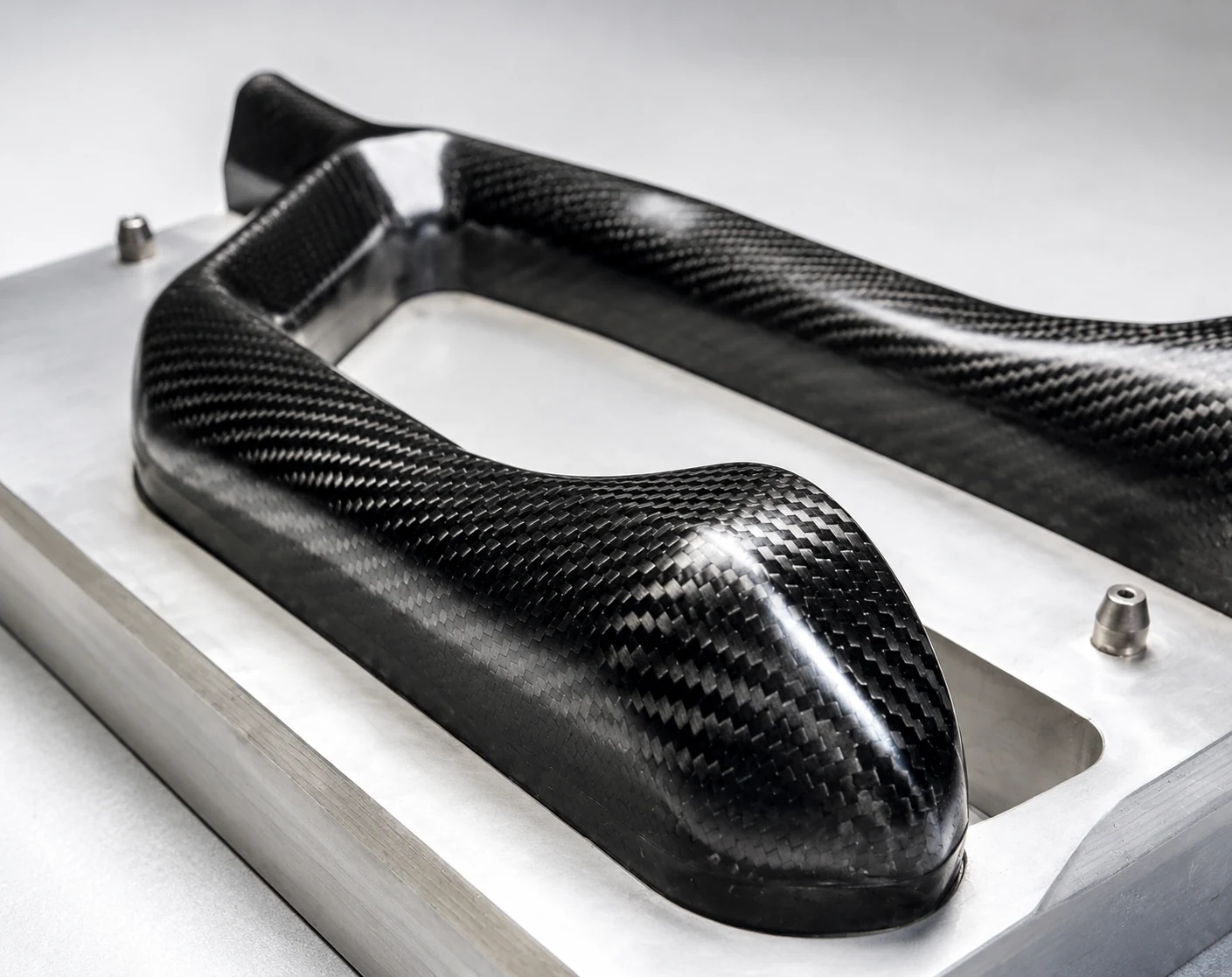
Fig. 06-A — First article, UV-protective clear coat
Verify the Product Route With Evidence That Matches the Finished Part
Generic “high quality” language does not tell a buyer whether a tube will accept its insert, a panel will arrive with closed edges or a fitted part will align with the vehicle reference. Define the governing version, critical characteristics, checking method, evidence, approver and release condition for the product being purchased.
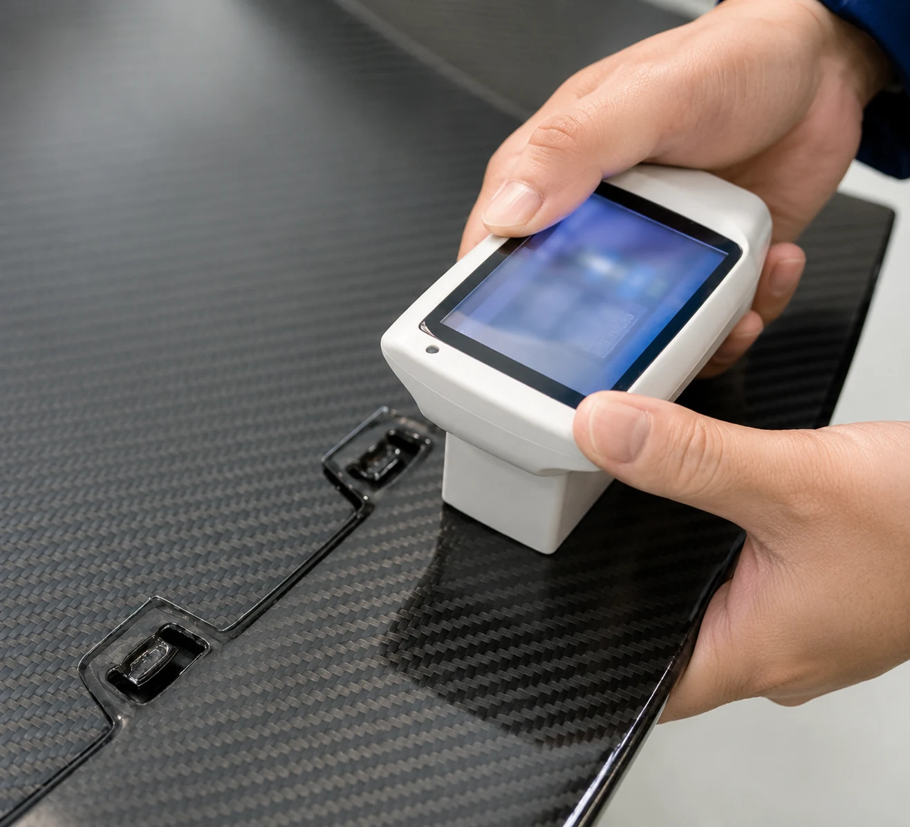
Fig. 07-A — Feature and appearance review before release
Use this sequence before release:
identify the governing drawing, CAD file, specification, sample or installation reference;
mark the dimensions, interfaces, visible surfaces and other characteristics that decide whether the product is usable;
agree the measurement or comparison method, sampling basis and record where required;
name who approves the sample, fitment, appearance or deviation; and
define the condition for production or shipment release and the protection required through delivery.
Not every order needs every report. A tube with drawing-defined holes may need first-article and dimensional evidence. A cored panel may need edge, insert and internal-condition evidence selected for that construction. A fitted hood may need vehicle-reference fitment and visible-surface approval. The quotation and project quality plan state which checks and customer-facing records are included.
This product-matched chain helps keep an unapproved dimension, surface or packing condition from reaching assembly. It also gives both parties the same basis for deciding whether a part can ship, needs documented review or must be corrected before release.
Start With the Best Reference You Have, Then Close the Gaps That Change the Route
You do not need a perfect production file to begin. You do need to separate confirmed facts from estimates and open decisions so an early reference is not mistaken for the final manufacturing definition.
For structural forms, send the section, wall or solid condition, length, end features and load or interface information.
For flat products, send the outline, thickness, construction, edges, inserts and finished machining state.
For fitted parts, identify the vehicle or equipment reference, installation position, mounting points and adjacent surfaces.
For custom or forged parts, include the best geometry, visible-face target, inserts, quantity and intended function available.
NEXWAVE returns the likely product and supply route, the decisions still open, the information that blocks a reliable quotation or manufacturing release, and the proposed included-work basis. This moves an incomplete inquiry forward without hiding assumptions that could later require a second sample, new tooling or another quotation round.
Product Selection FAQ
Yes. Approximate size, intended use and quantity are enough to begin a family review, although exact availability and supplied state remain product-specific. Send those three items and NEXWAVE will identify the most relevant route and the next dimensions to confirm.
Often, when the local geometry and load path support it. Cutting, holes, slots, countersinks, inserts, bonding or other features can change both feasibility and inspection. Send the feature drawing or mating-part information so NEXWAVE can confirm a modified standard product or move the work to custom review.
No. Base-form availability, material, tooling, complexity, quantity, inspection and current capacity create a product-specific commercial plan. Identify the likely family, quantity and required date so the quotation can state the applicable MOQ and schedule basis.
Yes, for an initial review. A sample or clear photograph can identify the likely route, but hidden geometry, mounting points and critical dimensions still need a controlled reference before manufacture. Send the original item, multiple views, one known dimension and the intended use so NEXWAVE can return the missing-information list.
Request Product Dimensions and a Quote
Send the product or application, the best drawing, CAD file, sample or photographs available, the dimensions or interfaces that matter, the intended use, quantity and required delivered state. NEXWAVE will identify the relevant product route, the open decisions and the work that should be included in the quotation.